Maytag MMMF8030P Bump Out Kit Installation Instructions - Page 8
Drill Holes in Rear Wall
 |
View all Maytag MMMF8030P manuals
Add to My Manuals
Save this manual to your list of manuals |
Page 8 highlights
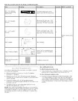
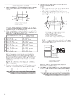
Below steps are for roof venting installation only, skip this steps if for recirculation venting or wall venting installation 3. Cut 3/4 (1.9 cm) hole at one corner of the shaded retangular area "F" on the upper cabinet template. 4. Using a keyhole saw, cut out the rectangular area. NOTE: If the front edge of the upper cabinet is lower than the back edge, lower the wall template so that its top is level with the front edge of the cabinet. Installation for No Wall Studs at End Holes (See figure 2 in the "Locate Wall Studs" section) 1. Drill two 5/8" (1.6 cm) holes through the wall at both end holes (A and B). 2. Drill four 3/16" (5 mm) lag screw hole(s), two into the wall studs at the holes (D and E), and two into the wall at the holes (H and J). F F. Roof Venting Cutout Area Drill Holes in Rear Wall In addition to being installed on at least one wall stud, the mounting plate must attach to the wall at both end holes. If the end holes are not over wall studs, use two 3/16-24 x 3" round head bolts with toggle nuts; if one end hole is over a wall stud, use one lag screw and one 3/16-24 x 3" round-head bolt with toggle nut; or if both end holes are over wall studs, use two lag screws. Following are four installation configurations. Installation for No Wall Studs at End Holes (See figure 1 in the "Locate Wall Studs" section) 1. Drill two 5/8" (1.6 cm) holes through the wall at both end holes (A and B). 2. Drill four 3/16" (5 mm) lag screw hole(s), two into the wall studs at the holes (D and E), and two into the wall at the holes (H and J). C F F A B H D E J A and B. Two End Holes C. Wall Template D, E, H, and J. Four Lag Screw Holes F. Wall Stud Installation for No Wall Studs at End Holes (See figure 3 in the "Locate Wall Studs" section) 1. Drill one 5/8" (1.6 cm) hole through the wall at end holes (A). 2. Drill five 3/16" (5 mm) lag screw hole(s), one into the wall studs at the hole (D), and four into the wall at the holes (B, E, H, and, J). C F A H D F B E J A and B. Two End Holes C. Wall Template D, E, H, and J. Four Lag Screw Holes F. Wall Stud C F F A B H D E J A. End Holes B, E, H, and J. Five Lag Screw Holes C. Wall Template F. Wall Stud 8
-
 1
1 -
2
-
 3
3 -
 4
4 -
 5
5 -
 6
6 -
 7
7 -
 8
8 -
 9
9 -
 10
10 -
 11
11 -
 12
12 -
 13
13 -
14
-
15
-
16
-
17
-
18
-
19
-
20
-
21
-
22
-
23
-
24
-
25
-
26
-
27
-
28
-
29
-
30
-
31
-
32
-
33
-
34
-
35
-
36
 |
 |
