Maytag MMMF8030P Bump Out Kit Installation Instructions - Page 9
Prepare the Bump Out Mounting Plate
 |
View all Maytag MMMF8030P manuals
Add to My Manuals
Save this manual to your list of manuals |
Page 9 highlights
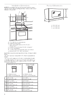
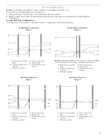
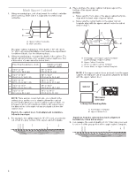
Installation for Wall Studs at Both End Holes (See figure 4 in the "Locate Wall Studs" section) 1. Drill four 3/16" (5 mm) lag screw hole(s) into the wall studs and wall at the hole (A, B, H, and J). 2. Drill 5/8" (1.6 cm) holes through the wall at the hole (D and E). 3. Select the right hooks for installation, there are two hooks on the M and N bracket, depends on the cabinet depth, select the right hook before installation. B A C C F A H D F B E J A and B. Two End Holes C. Wall Stud D, E, H, and J. Four Lag Screw Holes F. Wall Template Prepare the Bump Out Mounting Plate The default bump out mounting plate with L bracket is used for the upper cabinet larger than 13" and up to 14" depth. If your cabinet is 14" to 15", uninstall the L bracket, replace it with the M and N bracket. If your cabinet is 15" to 16", replace it with the P and R bracket. Use the right bracket before attach the bump out mounting plate onto the wall. If your upper cabinet is larger than 13" and up to 14" depth. 1. Take out the bump out mounting plate, which is folded, open it to 180 degree at plate. A. M Hook B. N Hook C. M and N Bracket Cabinet Depth M 14" to 141/2" (35.6 cm to 36.8 cm) N 141/2" to 15" (36.8 cm to 38.1 cm) 4. For example, the cabinet depth is 143/4", choose the N hook, and put the N hooks facing out. A A. N Hook 5. Fasten M and N bracket with the screws which uninstalled in step 2. 2. Attach the bump out mounting plate to wall, follow the steps in "Attach Bumpt Out Mounting Plate to Wall" section. If your upper cabinet is larger than 14" and up to 15" depth. 1. Take out the bump out mounting plate, which is folded, open it to 180 degree at plate. A A. Screws If your upper cabinet is larger than 14" and up to 15" depth. 1. Take out the bump out mounting plate, which is folded, open it to 180 degree at plate. 2. Uninstall the L bracket from the plate. Keep the L bracket for future use. A B 2. Uninstall the L bracket from the plate. Keep the L bracket for future use. A B C A. L Brackets B. Plate C. Screws C A. L Brackets B. Plate C. Screws 9
-
 1
1 -
2
-
3
-
 4
4 -
 5
5 -
 6
6 -
 7
7 -
 8
8 -
 9
9 -
 10
10 -
 11
11 -
 12
12 -
 13
13 -
 14
14 -
15
-
16
-
17
-
18
-
19
-
20
-
21
-
22
-
23
-
24
-
25
-
26
-
27
-
28
-
29
-
30
-
31
-
32
-
33
-
34
-
35
-
36
 |
 |
