McAfee IIP-S41K-NA-100I Product Guide
McAfee IIP-S41K-NA-100I - IntruShield 4010 Sensor Appliance Manual
 |
View all McAfee IIP-S41K-NA-100I manuals
Add to My Manuals
Save this manual to your list of manuals |
McAfee IIP-S41K-NA-100I manual content summary:
- McAfee IIP-S41K-NA-100I | Product Guide - Page 1
IntruShield Sensor 4000 Product Guide revision 7.0 McAfee® IntruShield® IPS IntruShield Sensor 4000 version 4.1 McAfee® Network Protection Industry-leading intrusion prevention solutions - McAfee IIP-S41K-NA-100I | Product Guide - Page 2
of the University of California, (C) 1990, 1993, with code derived from software contributed to Berkeley by Chris Torek. Issued DECEMBER 2008 / IntruShield Sensor 4000 Product Guide 700-1549-00/ 7.0 - English - McAfee IIP-S41K-NA-100I | Product Guide - Page 3
Contents Preface v Introducing McAfee IntruShield IPS v About this guide ...v Contents of this guide...v Audience ...vi Conventions used in this guide ...vi Related Documentation...vii Contacting Technical Support...viii Chapter 1 An introduction to IntruShield sensors 1 What is an IntruShield - McAfee IIP-S41K-NA-100I | Product Guide - Page 4
Using fail-open hardware ...21 Cabling for in-line mode...22 Cabling for Tap mode ...22 Cabling I-4000 GBIC ports in external Tap mode 22 Cabling for SPAN mode...23 Cabling the I-4000 sensor to monitor in SPAN or hub mode 23 Cabling the failover interconnection ports 23 Index 26 iv - McAfee IIP-S41K-NA-100I | Product Guide - Page 5
documents for this guide and how to contact McAfee Technical Support. Introducing McAfee IntruShield IPS McAfee IntruShield delivers the most comprehensive, accurate, and scalable network IPS solution for mission-critical enterprise, carrier, and service provider networks, while providing unmatched - McAfee IIP-S41K-NA-100I | Product Guide - Page 6
, or the commands necessary to perform particular tasks. Conventions used in this guide This document uses the following typographical conventions: Convention Example Terms that identify fields, buttons, The Service field on the Properties tab specifies the tabs, options, selections, and name - McAfee IIP-S41K-NA-100I | Product Guide - Page 7
Configuration Guide • Sensor Configuration Guide-using CLI • Sensor Configuration Guide-using ISM • Sensor Configuration Guide-using ISM Wizard • Alerts & System Health Monitoring Guide • Reports Guide • IntruShield User-Defined Signatures Developer's Guide • IntruShield Troubleshooting Guide vii - McAfee IIP-S41K-NA-100I | Product Guide - Page 8
McAfee® IntruShield® IPS 4.1 IntruShield Sensor 4000 Product Guide Preface Contacting Technical Support • IntruShield Attack Description Guide • IntruShield Special Topics Guide • Database Tuning • Best Practices • Denial-of-Service • Sensor High Availability • Custom Roles Creation • In-line - McAfee IIP-S41K-NA-100I | Product Guide - Page 9
and prevention of intrusions, misuse, and distributed denial of service (DDoS) attacks. IntruShield sensors are specifically designed to handle later chapters of this guide. The ISM server is described in detail in IntruShield Security Manager, Getting Started Guide. Sensor functionality The primary - McAfee IIP-S41K-NA-100I | Product Guide - Page 10
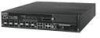
Sensor 4000 Product Guide An introduction to IntruShield sensors The IntruShield 4000 sensor This document describes the I-4000 sensor. The IntruShield 4000 sensor The IntruShield 4000 sensor (the I-4000), designed for high-bandwidth links, is equipped to support two full-duplex Ethernet - McAfee IIP-S41K-NA-100I | Product Guide - Page 11
Fail-Open Bypass Kit Guide. It is also used in troubleshooting situations where the sensor's internal flash is corrupted and you must reboot the sensor via the external compact flash. For more information, see the on-line KnowledgeBase at Mcafee Support - McAfee IIP-S41K-NA-100I | Product Guide - Page 12
McAfee® IntruShield® IPS 4.1 IntruShield Sensor 4000 Product Guide An introduction to IntruShield sensors The IntruShield 4000 sensor LED Status Description Power A Green Amber Power Supply A is functioning. Power Supply A is not functioning. Power B - McAfee IIP-S41K-NA-100I | Product Guide - Page 13
McAfee® IntruShield® IPS 4.1 IntruShield Sensor 4000 Product Guide An introduction to IntruShield sensors The IntruShield 4000 sensor LED Status Response Port Link Green Off Description The link is connected. The link is disconnected. 5 - McAfee IIP-S41K-NA-100I | Product Guide - Page 14
CHAPTER 2 Before you install Sensor specifications, safety measures, unpacking a sensor This chapter describes best practices for deployment of IntruShield sensors on your network. Topics include system requirements, site planning, safety considerations for handling the sensor, and usage - McAfee IIP-S41K-NA-100I | Product Guide - Page 15
McAfee® IntruShield® IPS 4.1 IntruShield Sensor 4000 Product Guide Before you install Sensor capacity for I-4000 sensor Mbps, Category 5 (Cat 5) OR Cat 5e cable can be used. Note: Throughout this guide, cabling specifications will be mentioned as Cat 5/Cat 5e. Sensor capacity for I-4000 sensor The - McAfee IIP-S41K-NA-100I | Product Guide - Page 16
McAfee® IntruShield® IPS 4.1 IntruShield Sensor 4000 Product Guide Before you install Network topology considerations Default number of supported UDP Flows Supported UDP Flows DoS Profiles SYN rate (64-byte packets per second) ACL Rules (refer to note below) 100,000 750,000 5000 1,000,000 1000 - McAfee IIP-S41K-NA-100I | Product Guide - Page 17
considerations, Planning and Deployment Guide. Safety measures The safety personnel should be allowed to install, replace, or service this equipment. • Before working on equipment that is installed and used in accordance with the instruction manual, may cause harmful interference to radio - McAfee IIP-S41K-NA-100I | Product Guide - Page 18
McAfee® IntruShield® IPS 4.1 IntruShield Sensor 4000 Product Guide Before you install Working with Fiber-optic ports Working with Fiber-optic ports • Fiber-optic ports (for example, FDDI, OC-3, OC-12, OC-48, ATM, - McAfee IIP-S41K-NA-100I | Product Guide - Page 19
McAfee® IntruShield® IPS 4.1 IntruShield Sensor 4000 Product Guide Before you install Unpacking the sensor • one power cord. McAfee provides a standard, 2m NEMA 5-15P (US) power cable (3 wire). International customers must procure a country-appropriate - McAfee IIP-S41K-NA-100I | Product Guide - Page 20
CHAPTER 3 Setting up the I-4000 sensor prior to configuration This chapter describes the process of setting up a sensor prior to configuring it via the ISM. Setup overview Setting up a sensor involves the following steps: 1 Positioning the sensor. (See Positioning the I-4000) 2 Installing the GBICs. - McAfee IIP-S41K-NA-100I | Product Guide - Page 21
McAfee® IntruShield® IPS 4.1 IntruShield Sensor 4000 Product Guide Setting up the I-4000 sensor prior to configuration Positioning the I-4000 ► To install the ears on the chassis, follow these steps: 1 Verify that you have - McAfee IIP-S41K-NA-100I | Product Guide - Page 22
McAfee® IntruShield® IPS 4.1 IntruShield Sensor 4000 Product Guide Setting up the I-4000 sensor prior to configuration Installing the I-4000 redundant power supply Mount the sensor by securing the ears to two posts or - McAfee IIP-S41K-NA-100I | Product Guide - Page 23
McAfee® IntruShield® IPS 4.1 IntruShield Sensor 4000 Product Guide Setting up the I-4000 sensor prior to configuration Installing the I-4000 redundant power supply 3 Place the power supply in the slot with the cable outlet - McAfee IIP-S41K-NA-100I | Product Guide - Page 24
IntruShield® IPS 4.1 IntruShield Sensor 4000 Product Guide Setting up the I-4000 sensor prior to configuration approved vendors, see the on-line KnowledgeBase, Mcafee Support Site. https://mysupport.mcafee.com These installation instructions provide information for installing a GBIC that uses two - McAfee IIP-S41K-NA-100I | Product Guide - Page 25
McAfee® IntruShield® IPS 4.1 IntruShield Sensor 4000 Product Guide Setting up the I-4000 sensor prior to configuration Cabling the sensor Removing a GBIC ► If you are removing a the sensor before powering it down. For more information on CLI commands, see Sensor Configuration Guide-using CLI. 17 - McAfee IIP-S41K-NA-100I | Product Guide - Page 26
CHAPTER 4 Attaching cables to the I-4000 Sensor Follow the steps outlined in this chapter to connect cables to the various ports on your sensor. Cabling the Console port The Console port is used for setup and configuration of the sensor. 1 For console connections, plug the DB9 Console cable - McAfee IIP-S41K-NA-100I | Product Guide - Page 27
McAfee® IntruShield® IPS 4.1 IntruShield Sensor 4000 Product Guide Attaching cables to the I-4000 Sensor Cabling the Response ports Name Baud rate Number of bits Parity Stop bits Flow Control Setting 9600 8 None 1 None - McAfee IIP-S41K-NA-100I | Product Guide - Page 28
Guide Attaching cables to the I-4000 Sensor Cabling the Management port Cabling the I-4000 Monitoring ports Connect to the network devices you will be monitoring via the sensor Monitoring ports. You can deploy sensors in the operating modes shown in the following table. Cabling instructions - McAfee IIP-S41K-NA-100I | Product Guide - Page 29
IntruShield® IPS 4.1 IntruShield Sensor 4000 Product Guide Attaching cables to the I-4000 Sensor Cabling needed to connect the switch to the sensor. This Kit is sold separately. Installation and troubleshooting instructions for the Kit can be found in the kit's documentation. For more details on - McAfee IIP-S41K-NA-100I | Product Guide - Page 30
Product Guide Attaching hardware and cable the sensor for fail-open functionality. For instructions, see the section later in this chapter. ► To connect list of approved 3rd party vendors, see the KnowledgeBase at Mcafee Support Site https://mysupport.mcafee.com. External tap mode requires a port - McAfee IIP-S41K-NA-100I | Product Guide - Page 31
® IntruShield® IPS 4.1 IntruShield Sensor 4000 Product Guide Cabling for SPAN mode Attaching cables to the The Sensor can be configured to run in in-line or SPAN/TAP mode. TCP reset is not supported when connected in TAP mode. Cabling I-4000 sensors for failover Gigabit ports 2A-and 2B are the - McAfee IIP-S41K-NA-100I | Product Guide - Page 32
IntruShield® IPS 4.1 IntruShield Sensor 4000 Product Guide Attaching cables to the I-4000 Sensor Cabling back online, the ports configured as fail-open will remain in 'Bypass' mode until the user manually puts them back to fail-open. Caution 1: Note that sensor outage breaks the link connecting the - McAfee IIP-S41K-NA-100I | Product Guide - Page 33
outage, again, varies depending on the device, and can range from a few seconds to more than a minute. Installation and troubleshooting instructions for the Kit can be found in the Quick Guide that accompanies the kit. For more information on the Optical kit, see Gigabit Optical Fail-Open Bypass Kit - McAfee IIP-S41K-NA-100I | Product Guide - Page 34
port Speed LED 4 A accomplishing fail-closed functionality 2 auxiliary port 2 B boot LED 4 C cabling 18, 19, 20, 23 cabling for failover 24 cabling instructions 18 cabling sensor for GBIC ports 23 cabling the auxiliary port 19 cabling the console port 19 cabling the sensors for failover - McAfee IIP-S41K-NA-100I | Product Guide - Page 35
T tap mode 23 Temp LED 4 U using fail-open hardware 25
-
 1
1 -
 2
2 -
 3
3 -
 4
4 -
 5
5 -
 6
6 -
 7
7 -
8
-
9
-
10
-
11
-
12
-
13
-
14
-
15
-
16
-
17
-
18
-
19
-
20
-
21
-
22
-
23
-
24
-
25
-
26
-
27
-
28
-
29
-
30
-
31
-
32
-
33
-
34
-
35
 |
 |

IntruShield Sensor 4000 Product Guide
revision 7.0
McAfee
®
Network Protection
Industry-leading intrusion prevention solutions
McAfee® IntruShield® IPS
IntruShield Sensor 4000
version 4.1