McAfee IIP-S41K-NA-100I Product Guide - Page 11
Front panel LEDs on the I-4000, One RS-232C Console port
 |
View all McAfee IIP-S41K-NA-100I manuals
Add to My Manuals
Save this manual to your list of manuals |
Page 11 highlights
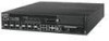
McAfee® IntruShield® IPS 4.1 IntruShield Sensor 4000 Product Guide An introduction to IntruShield sensors The IntruShield 4000 sensor 1 One 10/100 Management port, which is used for communication with the ISM server. This port has an assigned IP address. 2 One RS-232C Console port, which is used to set up and configure the sensor. 3 One RS-232C Auxiliary port, which may be used to dial in remotely to set up and configure the sensor. 4 Four monitoring GBIC ports, which enable you to monitor four SPAN ports, two fullduplex tapped segments, two segments in-line, or a combination (that is, one full-duplex segment, two SPAN ports). The monitoring interfaces of the I-4000 work in stealth mode, meaning they have no IP address and are not visible on the monitored segment. If you choose to run in failover mode, ports 2A and 2B are used to interconnect with a standby sensor. 5 Two response ports, which, when you are operating in SPAN mode, enable you to inject response packets back through a switch or router. 6 One External Compact Flash port. This port is used for two purposes. It is used to control optional fail-open hardware as described in the Gigabit Optical Fail-Open Bypass Kit Guide. It is also used in troubleshooting situations where the sensor's internal flash is corrupted and you must reboot the sensor via the external compact flash. For more information, see the on-line KnowledgeBase at Mcafee Support Site. https://mysupport.mcafee.com 7 Power Supply A (included). Power supply A is included with each sensor. The supply uses a standard IEC port (IEC320-C13). The supply uses a standard IEC port (IEC320-C13). McAfee provides a standard, 2m NEMA 5-15P (US) power cable (3 wire). International customers must procure a country-appropriate power cable. 8 Power Supply B (optional, purchased separately). Power supply B is a hot-swappable, redundant power supply. This power supply also uses a standard IEC320-C13 port, and you can use the McAfee-provided cable or acquire one that meets your specific needs. The I-4000 does not have internal taps; it must be used with a 3rd party external tap to run in tapped mode. Front panel LEDs on the I-4000 The front panel LEDs provide status information for the health of the sensor and the activity on its ports. The following table describes the front panel LEDs. 3
-
 1
1 -
2
-
3
-
4
-
5
-
 6
6 -
 7
7 -
 8
8 -
 9
9 -
 10
10 -
 11
11 -
 12
12 -
 13
13 -
 14
14 -
 15
15 -
 16
16 -
17
-
18
-
19
-
20
-
21
-
22
-
23
-
24
-
25
-
26
-
27
-
28
-
29
-
30
-
31
-
32
-
33
-
34
-
35
 |
 |
