McAfee M-2750 Product Guide - Page 8
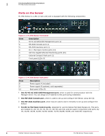
Ports on the Sensor, Description, One RJ-45 10/100/1000 Management port, One RS-232C Console port - sfp
 |
View all McAfee M-2750 manuals
Add to My Manuals
Save this manual to your list of manuals |
Page 8 highlights
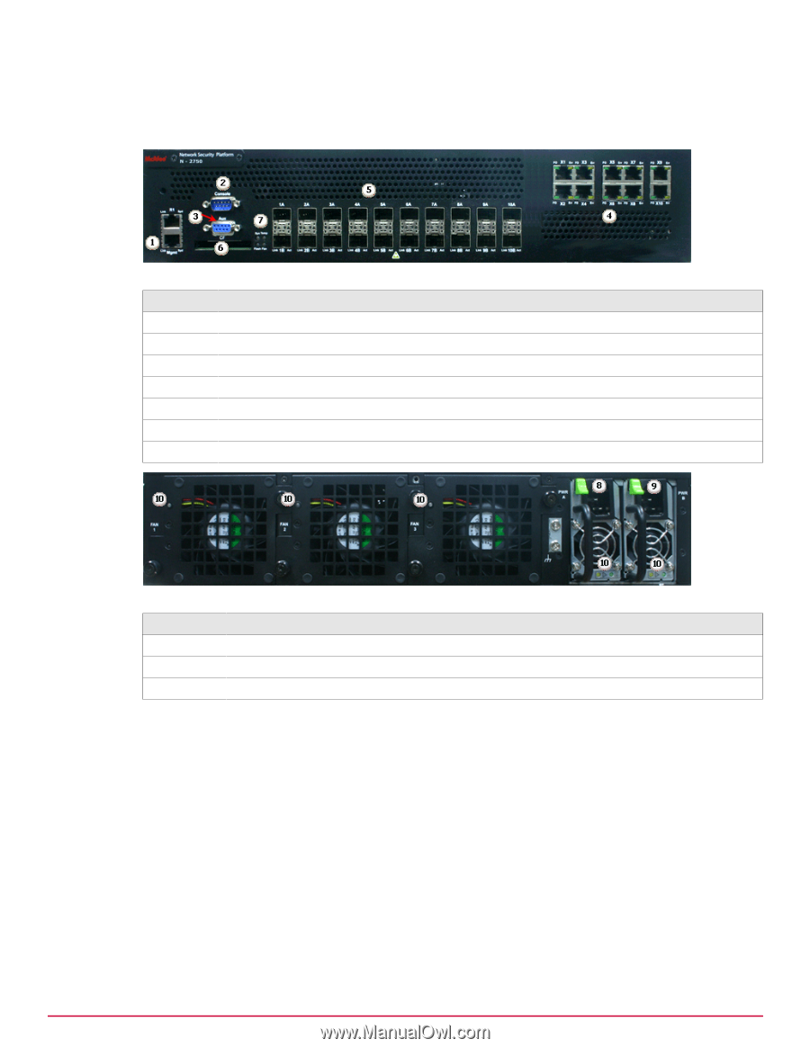
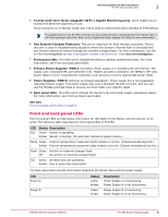
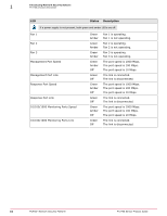
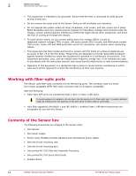
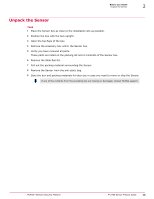
1 Introducing Network Security Sensors M-2750 physical description Ports on the Sensor M-2750 Sensor is a 2RU (2 rack unit) and is equipped with the following components: Figure 1-1 M-2750 Sensor front panel Item 1 2 3 4 5 6 7 Description RJ-45 10/100/1000 Management port (1) RS-232C Console port (1) RS-232C Auxiliary port (1) RJ-11 Fail-Open Control ports (10) SFP One Gigabit Ethernet Monitoring ports (20) External Compact Flash port (1) Front panel LEDs (4) Figure 1-2 M-2750 Sensor back panel Item 8 9 10 Description Power supply A (included) Power supply B (optional; sold separately) Back panel LEDs (5) 1 One RJ-45 10/100/1000 Management port, which is used for communication with the Manager server. You can assign an IP address to this port during installation. 2 One RS-232C Console port, which is used to set up and configure the Sensor using the CLI. 3 One RS-232C Auxiliary port, which may be used to dial in remotely to set up and configure the Sensor. 4 Ten RJ-11 Fail-Open Control ports, designed for use the Optical Fail-Open Bypass kit. The ports are marked X1, X2, X3, X4, X5, X6, X7, X8, X9, and X10, and are used in conjunction with ports 1A/ 1B, 2A/2B, 3A/3B, 4A/4B, 5A/5B, 6A/6B, 7A/7B, 8A/8B, 9A/9B, and 10A/10B, respectively. 8 McAfee® Network Security Platform M-2750 Sensor Product Guide
-
 1
1 -
2
-
 3
3 -
 4
4 -
 5
5 -
 6
6 -
 7
7 -
 8
8 -
 9
9 -
 10
10 -
 11
11 -
 12
12 -
 13
13 -
14
-
15
-
16
-
17
-
18
-
19
-
20
-
21
-
22
-
23
-
24
-
25
-
26
-
27
-
28
-
29
-
30
-
31
-
32
-
33
-
34
-
35
-
36
 |
 |