Meade LX850 User Manual - Page 14
Attach Mount Assembly to Tripod, Setting Latitude - 14
 |
View all Meade LX850 manuals
Add to My Manuals
Save this manual to your list of manuals |
Page 14 highlights
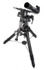
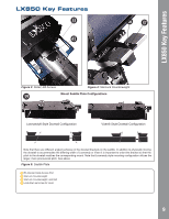
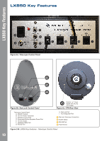
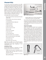
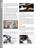
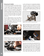
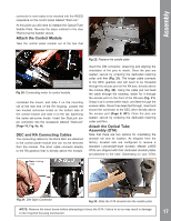
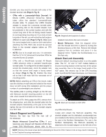
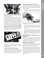
AutoStar #497 HAsAsNeDmBbOlyX Loosen the two (2) leg lock-knobs on each tripod leg. Adjust the height of the tripod to the desired height and with the tripod head approximately level, tighten the leg locks. Tighten the locks to a firm feel only; do not over tighten. Slide the threaded rod through the spreader and then slide this assembly through the central mounting hole in the tripod head. Place the threaded rod through central mounting hole far enough so that the retaining clip channel is exposed. Press fit the retaining clip through the machined channel. The retaining clip will now hold the spreader bar for easy assembly. Attach Mount Assembly to Tripod Remove the equatorial mount assembly from the shipping carton. You may notice as you are removing the mount that the RA and DEC clutches are not locked. This is intentionally done at the factory to prevent possible damage to the gears while in transit. Fig 11: Tighten Clutch. assembly. DO NOT OVERTIGHTEN. Place the mount on the tripod head. At this point it is advisable to either use one hand, or (ideally) enlist someone else's hand, to steady the mount while it is fastened to the tripod. Orient the mount so that it aligns with the poles, control panel facing the South pole (North pole in the southern hemisphere). Push the threaded rod up and secure the mount to the tripod by tightening the central lock knob. Use the supplied custom utility tool to secure it to a "tight" fit. If properly secured, the spreader bar will make contact with all three tripod legs and the mount will not slip. Fig 9: Mount in Box Manually tighten down the three (3) RA and three (3) DEC clutch lock bolts using the supplied 5/16" hex head wrench to facilitate easier handling during Setting Latitude Refer to the latitude chart on Appendix D, page 54. Listed are the latitude for most major cites world wide. Locate your city in the chart and note its latitude. If your city is not listed follow the formula to calculate your locations latitude. Loosen the Attitude Adjustment Lock Knob (fig. 18, page 7). Locate the Attitude Adjustment Knob (fig. 17, page 7) and the Latitude Scale (fig. 30, page 8). The DEC Clutch: Two of three shown, third on opposite side (not visible). RA Clutch: Two of three shown, third on opposite side (not visible). Fig 10: DEC and RA Clutch Locations 14 Fig 12: Attach Counterweight Shaft.
-
 1
1 -
2
-
3
-
4
-
5
-
6
-
7
-
8
-
 9
9 -
 10
10 -
 11
11 -
 12
12 -
 13
13 -
 14
14 -
 15
15 -
 16
16 -
 17
17 -
 18
18 -
 19
19 -
20
-
21
-
22
-
23
-
24
-
25
-
26
-
27
-
28
-
29
-
30
-
31
-
32
-
33
-
34
-
35
-
36
-
37
-
38
-
39
-
40
-
41
-
42
-
43
-
44
-
45
-
46
-
47
-
48
-
49
-
50
-
51
-
52
-
53
-
54
-
55
-
56
-
57
-
58
-
59
-
60
 |
 |
