Motorola 549478-001-00 User Guide - Page 35
Enable line power
 |
UPC - 766796451012
View all Motorola 549478-001-00 manuals
Add to My Manuals
Save this manual to your list of manuals |
Page 35 highlights
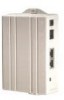
RADIUS network authenticated login Step 2 Connect 50mm (2") cable (supplied) between bottom mounted RJ11 port on the MC-802 and the existing RJ11 jack. Step 3 Attach the MC-802 to the Mounting Adapter using the supplied 6/32 thread forming screws 6/32 thread forming screws 6/32 thread forming screws Step 4 1. Connect the local AC power adapter to the WallPlate 2. Connect the analog phone to the RJ11 phone jack Step 5 After WallPlate Link LED is solid, verify the device is connected using the command, "show int dsl status". It is best to have a technician in the phone room directly connected to the T3 Switch to coordinate and enable Line Power. Enable line power Determine which port is being installed From the CLI, enter this command: Motorola, Inc. 570510-001-00 rev A Page 35 of 50
-
 1
1 -
2
-
3
-
4
-
5
-
6
-
7
-
8
-
9
-
10
-
11
-
12
-
13
-
14
-
15
-
16
-
17
-
18
-
19
-
20
-
21
-
22
-
23
-
24
-
25
-
26
-
27
-
28
-
29
-
 30
30 -
 31
31 -
 32
32 -
 33
33 -
 34
34 -
 35
35 -
 36
36 -
 37
37 -
 38
38 -
 39
39 -
 40
40 -
41
-
42
-
43
-
44
-
45
-
46
-
47
-
48
-
49
-
50
 |
 |
