NEC LCD4610-BK MultiSync LCD4010/4610 Users Manual - Page 11
Terminal Panel - multisync
 |
UPC - 805736012231
View all NEC LCD4610-BK manuals
Add to My Manuals
Save this manual to your list of manuals |
Page 11 highlights
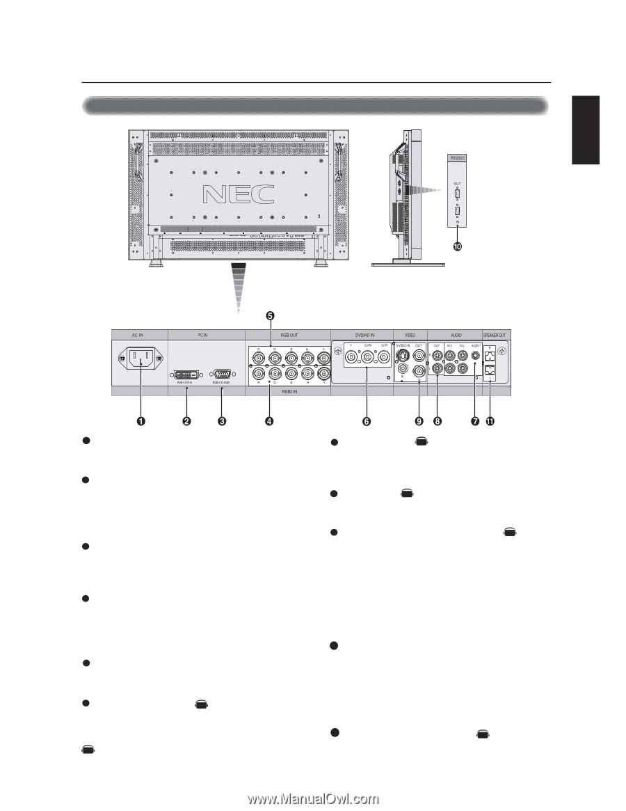
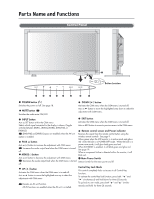
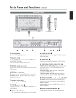
Parts Name and Functions -continued Terminal Panel English 1 AC IN connector Connects with the supplied power cord. 2 RGB 1 IN (DVI-D) To input digital RGB signals from a computer or HDTV device having a digital RGB output. * This connector does not support analog input. 3 RGB 2 IN (mini D-Sub 15 pin) To input analog RGB signals from a personal computer or other RGB equipment. 4 RGB 3 [R, G, B, H, V] (BNC) IN connector: To input the analog RGB signals or signals from other RGB equipment. A Sync-on-Green signal can be connected to the G connector. 5 RGB OUT connector (BNC) To output the signal from the RGB 3 IN connector. 6 DVD/HD connector (BNC) AV Connecting equipment such as a DVD player, HDTV device, or Laser disc player. AV Denotes an AV unit function. All AV functions are enabled when the AV unit is installed. 7 AUDIO IN 1,2,3 AV Input audio signal from external equipment such as a computer, VCR or DVD player. 8 AUDIO OUT AV Output the audio signal from the selected AUDIO IN source. 9 VIDEO INPUT/OUTPUT CONNECTOR AV VIDEO IN connector (BNC and RCA): Input a composite video signal. BNC and RCA are not available at the same time. (Use only one input). VIDEO OUT connector (BNC): Output the composite video signal from the VIDEO IN source. S-VIDEO IN connector (DIN 4 pin): Input the S-video (Y/C separate signal). See page 26, S-VIDEO MODE SETTING. 10 EXTERNAL CONTROL (mini D-Sub 9 pin) RS-232C In connector: Input signal from control equipment such as a computer or the output from a different MultiSyc LCD4010/ MultiSync LCD4610. Out connector: To connect multiple MultiSync LCD4010/ MultiSync LCD4610. 11 EXTERNAL SPEAKER TERMINAL AV Outputs the audio signal from the selected audio source. English-7
-
 1
1 -
2
-
3
-
4
-
5
-
 6
6 -
 7
7 -
 8
8 -
 9
9 -
 10
10 -
 11
11 -
 12
12 -
 13
13 -
 14
14 -
 15
15 -
 16
16 -
17
-
18
-
19
-
20
-
21
-
22
-
23
-
24
-
25
-
26
-
27
-
28
-
29
-
30
-
31
-
32
-
33
-
34
-
35
-
36
-
37
-
38
-
39
-
40
-
41
-
42
-
43
-
44
-
45
-
46
-
47
-
48
-
49
-
50
-
51
-
52
-
53
-
54
-
55
-
56
-
57
-
58
-
59
-
60
-
61
-
62
-
63
-
64
-
65
-
66
-
67
-
68
-
69
-
70
-
71
-
72
-
73
-
74
-
75
-
76
-
77
-
78
-
79
-
80
-
81
-
82
-
83
-
84
-
85
-
86
-
87
-
88
 |
 |