Netgear CG3000-1STAUS CG3000-1STAUS User Guide - Page 6
Back Panel Description - usb
 |
View all Netgear CG3000-1STAUS manuals
Add to My Manuals
Save this manual to your list of manuals |
Page 6 highlights
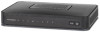
Back Panel Description The following picture shows the description and function of the back panel components on your modem. 1 2 3 4 56 1. Telephone 1 and 2 2. LAN 3. USB 4. CABLE 5. POWER 6. ON/OFF SWITCH RJ-11 telephone ports connect to home telephone wiring to conventional telephones or fax machines Four RJ-45 Ethernet ports connect to the Ethernet port on your PC or your home network Connects to a printer or mass storage device. This feature is currently disabled. This can only be made active by a remote software upgrade Note: Your service does not support data connections via USB, please connect your computer via the Ethernet port to ensure optimal connection speed. F-connector connects to an active cable signal from Optus Connects your residential gateway to the AC power adapter that is provided with your WiFi Cable modem Caution: Avoid damage to your equipment. Only use the power supply that is provided with your modem Turns the device on or off. It is recommended that the device remains on at all times. 4 BACK PANEL DESCRIPTION 1382777E 0411 166321.indd 4 7/04/11 10:42 AM
-
 1
1 -
 2
2 -
 3
3 -
 4
4 -
 5
5 -
 6
6 -
 7
7 -
 8
8 -
 9
9 -
 10
10 -
 11
11 -
 12
12 -
13
-
14
-
15
-
16
 |
 |
