Netgear EN516 EN516 Installation Guide - Page 41
BNC Connector
 |
View all Netgear EN516 manuals
Add to My Manuals
Save this manual to your list of manuals |
Page 41 highlights
Installation Guide for the Model EN516 Ethernet Hub Table C-2 lists the AUI connector pin assignments. Table C-2. AUI connector pin assignments Pin 1, 4, 11, 14, 15 2 3 5 6 7, 8 9 10 12 13 Signal Ground CI-A DO-A DI-A + 12V DC return Not used CI-B DO-B DI-B + 12V DC (500 mA maximum) BNC Connector The BNC connector for the Model EN516 hub supports 10 Mbps data transmission and connects the hub to other devices. Figure C-3 illustrates the parts of the BNC connector. 1 2 7201 Key: 1 = Center conductor 2 = Ground shield Figure C-3. BNC connector Connector Pin Assignments C-3
-
 1
1 -
2
-
3
-
4
-
5
-
6
-
7
-
8
-
9
-
10
-
11
-
12
-
13
-
14
-
15
-
16
-
17
-
18
-
19
-
20
-
21
-
22
-
23
-
24
-
25
-
26
-
27
-
28
-
29
-
30
-
31
-
32
-
33
-
34
-
35
-
 36
36 -
 37
37 -
 38
38 -
 39
39 -
 40
40 -
 41
41 -
 42
42 -
 43
43 -
 44
44 -
 45
45 -
 46
46
 |
 |
Installation Guide for the Model EN516 Ethernet Hub
Connector Pin Assignments
C-3
Table C-2 lists the AUI connector pin assignments.
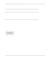
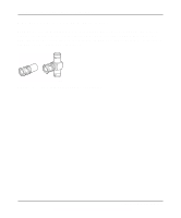
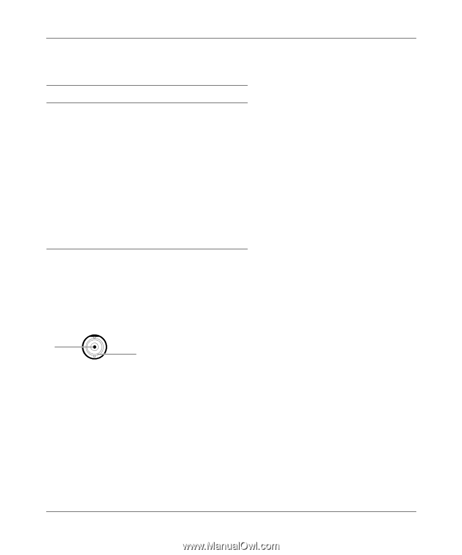
BNC Connector
The BNC connector for the Model EN516 hub supports 10 Mbps data transmission and connects
the hub to other devices. Figure C-3 illustrates the parts of the BNC connector.
Key:
1 = Center conductor
2 = Ground shield
Figure C-3.
BNC connector
Table C-2.
AUI connector pin assignments
Pin
Signal
1, 4, 11, 14, 15
Ground
2
CI-A
3
DO-A
5
DI-A
6
+ 12V DC return
7, 8
Not used
9
CI-B
10
DO-B
12
DI-B
13
+ 12V DC (500 mA
maximum)
7201
1
2