Netgear FE508 Installation Guide - Page 20
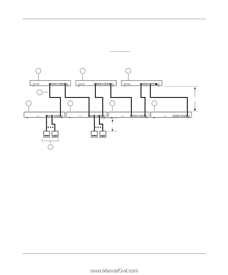
Extending a Network, Ethernet hubs integrated with three NETGEAR Model FS508 Fast Ethernet switches.
 |
UPC - 606449000146
View all Netgear FE508 manuals
Add to My Manuals
Save this manual to your list of manuals |
Page 20 highlights
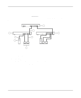
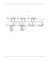
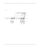
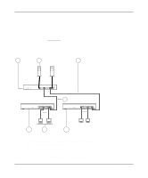
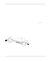
Installation Guide for the Model FS508 Fast Ethernet Switch Extending a Network Ethernet specifications limit the length of cable between hubs and PCs to 100 meters for a total diameter of 200 meters. By adding Fast Ethernet switches between hubs, the network is expanded by 200 Mbps with the addition of each switch. Figure 3-3 illustrates a network of FE508 Fast Ethernet hubs integrated with three NETGEAR Model FS508 Fast Ethernet switches. 1 1 1 2 100 m 3 3 3 3 100 m 4 Key: 1 = Model FS508 Fast Ethernet switch (Normal/Uplink push button set to Uplink position) 2 = 100 Mbps connection 3 = Model FE508 Fast Ethernet hub (Normal/Uplink push button set to Uplink position) 4 = PCs with 100 Mbps connection Figure 3-3. Using the Model FS508 switch for network extension 7503EA 3-4 Applications
-
 1
1 -
2
-
3
-
4
-
5
-
6
-
7
-
8
-
9
-
10
-
11
-
12
-
13
-
14
-
 15
15 -
 16
16 -
 17
17 -
 18
18 -
 19
19 -
 20
20 -
 21
21 -
 22
22 -
 23
23 -
 24
24 -
 25
25 -
26
-
27
-
28
-
29
-
30
-
31
-
32
-
33
-
34
-
35
-
36
-
37
-
38
-
39
-
40
-
41
-
42
 |
 |