Netgear FE508 Installation Guide - Page 7
s, C-1.
 |
UPC - 606449000146
View all Netgear FE508 manuals
Add to My Manuals
Save this manual to your list of manuals |
Page 7 highlights
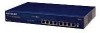
Figures Figure 2-1. Figure 2-2. Figure 2-3. Figure 3-1. Figure 3-2. Figure 3-3. Figure 3-4. Figure 3-5. Figure 4-1. Figure B-1. Figure C-1. Figure C-2. Figure C-3. Front panel of the Model FS508 switch 2-1 The vista RJ-45 connector with built-in LEDs 2-2 Rear panel of the Model FS508 switch 2-4 Using the Model FS508 switch for desktop switching 3-2 Model FS508 switch used as a segment switch 3-3 Using the Model FS508 switch for network extension 3-4 Bridging 10 Mbps networks to 100 Mbps networks 3-5 High-bandwidth file server connection 3-6 Attaching mounting brackets to the Model FS508 switch 4-3 RJ-45 plug and vista RJ-45 connector with built-in LEDs B-1 Straight-through twisted pair cable C-3 Crossover twisted pair cable C-3 Category 5 UTP patch cable with male RJ-45 plug at each end C-4 Figures vii
-
 1
1 -
 2
2 -
 3
3 -
 4
4 -
 5
5 -
 6
6 -
 7
7 -
 8
8 -
 9
9 -
 10
10 -
 11
11 -
 12
12 -
13
-
14
-
15
-
16
-
17
-
18
-
19
-
20
-
21
-
22
-
23
-
24
-
25
-
26
-
27
-
28
-
29
-
30
-
31
-
32
-
33
-
34
-
35
-
36
-
37
-
38
-
39
-
40
-
41
-
42
 |
 |