Netgear FS516 FS516 Installation Guide - Page 15
LEDs, Link status - power supply
 |
View all Netgear FS516 manuals
Add to My Manuals
Save this manual to your list of manuals |
Page 15 highlights
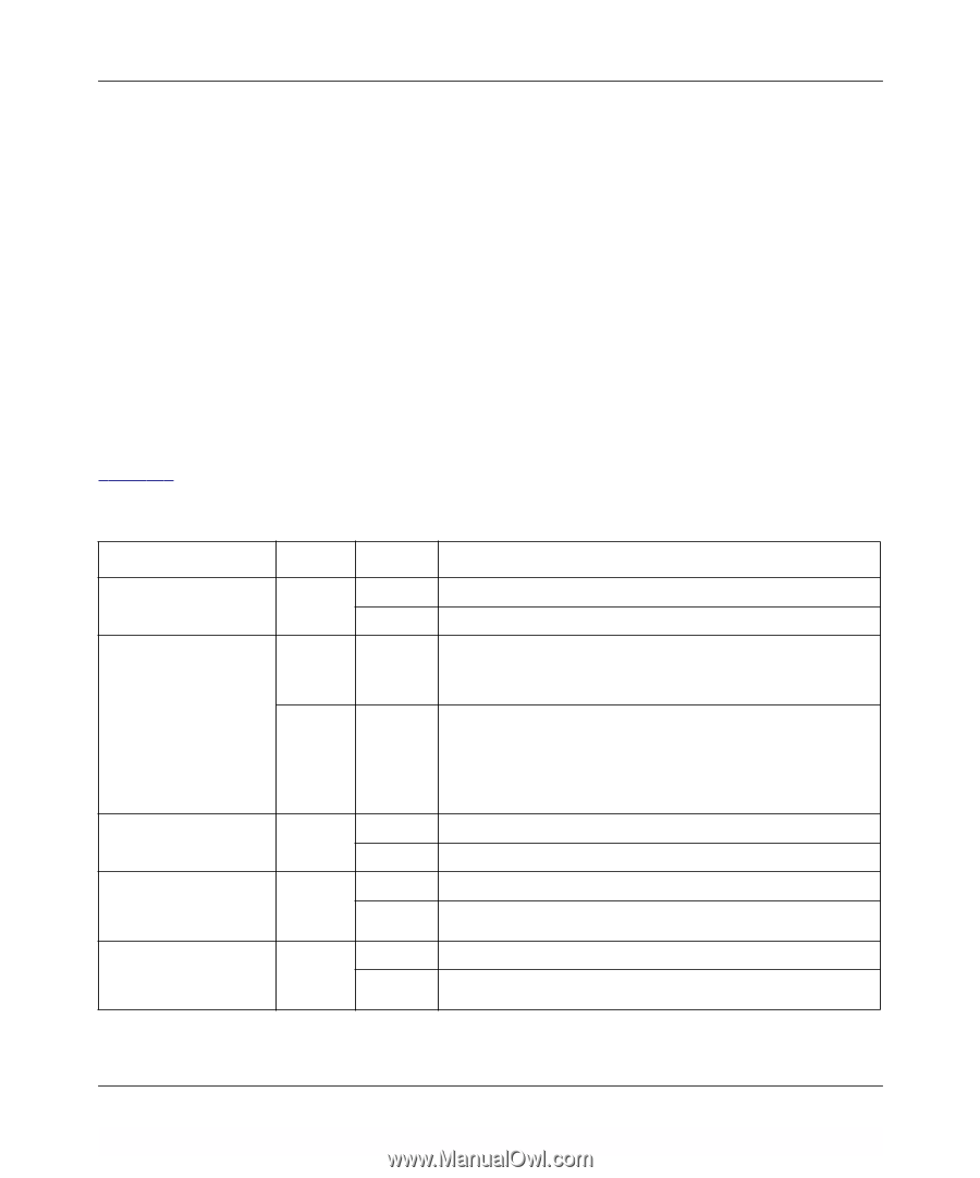
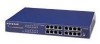
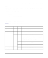
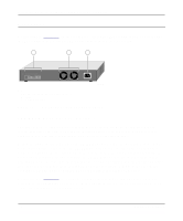
Installation Guide for the Model FS516 Fast Ethernet Switch LEDs The LEDs on the front panel of the switch and two vista LEDs on each RJ-45 connector allow you to identify the following information: • Status of the switch power supply • For each 10/100 Ethernet port: - Link status - Data transmission or receive activity - Collision occurrence - Full-duplex or half-duplex mode - 10 Mbps or 100 Mbps speed transmission Table 2-1 describes each LED on the front panel of the switch. Table 2-1. LED Descriptions Label Power ACT/COL Color Green Green Yellow 100 Mbps Green Link (located at the top Green left corner of each 10/100 Mbps port) FDX (located at the top Green right corner of each 10/100 Mbps port) Activity On Off Blinking Blinking On Off On Off Description Power is supplied to the switch. Power is disconnected. Packet transmission or reception is occurring on the port. The blinking action corresponds to the number of packets that are transmitted or received. Data collisions are occurring on the port. The blinking action corresponds to the number of collisions. When a collision occurs, the connected device pauses and transmits again after waiting a specified time. Note that occasional collisions are normal. The port is operating at 100 Mbps. The port is operating at 10 Mbps. A valid link is established on the port. A link is not established on the port. On The port is operating in full-duplex mode. Off The port is operating in half-duplex mode. Physical Description 2-3
-
 1
1 -
2
-
3
-
4
-
5
-
6
-
7
-
8
-
9
-
 10
10 -
 11
11 -
 12
12 -
 13
13 -
 14
14 -
 15
15 -
 16
16 -
 17
17 -
 18
18 -
 19
19 -
 20
20 -
21
-
22
-
23
-
24
-
25
-
26
-
27
-
28
-
29
-
30
-
31
-
32
-
33
-
34
-
35
-
36
-
37
-
38
-
39
-
40
-
41
-
42
 |
 |