Netgear FS516 FS516 Installation Guide - Page 27
Verifying Installation, and connect the other end of the power cord to a wall receptacle. - no power
 |
View all Netgear FS516 manuals
Add to My Manuals
Save this manual to your list of manuals |
Page 27 highlights
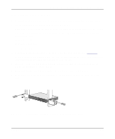
Installation Guide for the Model FS516 Fast Ethernet Switch 2. Set the FDX or AUTO switches on the rear panel for the duplex mode. A hub and repeater use a common collision domain for all communications and cannot support full-duplex mode. When connecting any of the 10/100 Mbps ports on the switch to a hub, set the port to AUTO. The switch must also be set to AUTO when connecting to any device that does not use NWay auto-negotiation to detect the operating mode. Setting the toggle switch to AUTO will cause the port to default to half-duplex mode when connecting to a port that does not use NWay auto-negotiation. When connecting to a PC, a server, or another switch, the duplex setting for the port must be the same as the duplex setting on the PC, server, or other switch. To set the 10/100 Mbps ports for the selected duplex mode: • Move the toggle switch into the down position (to AUTO) for auto-duplex mode. The 10/100 Mbps ports will negotiate and automatically determine the duplex mode based on the mode of the connected port. If the connected port cannot autonegotiate, the 10/100 Mbps port will default to half-duplex. The factory setting of the duplex toggle switches is AUTO. • Move the toggle switch into the up position (to FDX) for full-duplex mode.The duplex switch must be set to FDX if you are connecting to legacy full-duplex 100 Mbps devices that do not generate signals indicating duplex mode. If the duplex switch is set to AUTO mode when connecting to legacy full-duplex 100 Mbps devices, the 10/100 Mbps ports will default to half-duplex mode because the port does not receive the proper signal. 3. Connect one end of the power cord to the power outlet on the back panel of the switch, and connect the other end of the power cord to a wall receptacle. The switch automatically selects the proper voltage in the range of 100 to 240 volts. The Power LED lights and the cooling fans start up after successfully completing the self-tests. The switch is now operational. Verifying Installation Verify network communications by ensuring that all the necessary connections have been made, that all connected resources can be accessed, and that the LED indicators on the switch are functioning properly. For additional information, refer to Chapter 5, "Troubleshooting." Installation 4-5
-
 1
1 -
2
-
3
-
4
-
5
-
6
-
7
-
8
-
9
-
10
-
11
-
12
-
13
-
14
-
15
-
16
-
17
-
18
-
19
-
20
-
21
-
 22
22 -
 23
23 -
 24
24 -
 25
25 -
 26
26 -
 27
27 -
 28
28 -
 29
29 -
 30
30 -
 31
31 -
 32
32 -
33
-
34
-
35
-
36
-
37
-
38
-
39
-
40
-
41
-
42
 |
 |