Netgear FSM726E FSM726E Hardware Installation Guide - Page 12
Table 1., LED Descriptions for FSM726E - 100
 |
UPC - 606449063820
View all Netgear FSM726E manuals
Add to My Manuals
Save this manual to your list of manuals |
Page 12 highlights
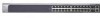
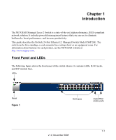
Managed Layer 2 Switch with 2 Gigabit Ethernet Ports FSM726E Hardware Installation Guide The following table describes the LEDs on the front panel of the switch. Table 1. LED Descriptions for FSM726E LED PWR (Power) FAN 10/100 (port 1 to 24) (1 LED per port) SFP ports (100/1000 Mbps) 10/100/1000M ports (1 LED per port) Description • Solid green. Power is supplied and the switch is working. • Blinking green. Power-on self-test (POST) in progress. • Solid yellow. System is booting up. • Blinking yellow. POST, CPU, or power supply has failed • Off. Power is disconnected. • Yellow. The fan has failed. • Green. The fan is operating normally. Link/ACT LED • Off. No link is established on the port. • Solid green. A valid 100 Mbps link is established on the port. • Blinking green. The port is sending or receiving packets at 100M. • Solid yellow. A valid 10Mbps link is established on the port. • Blinking yellow. The port is sending or receiving packets at 10 Mbps. Link/ACT LED • Off: No link is established on this port. • Solid green. A valid 1000 Mbps SFP module link is established on the port. • Blinking green. The port is sending or receiving packets at 1000 Mbps. • Solid Yellow. A valid 100Mbps SFP module link is established on the port. • Blinking Yellow. The port is sending or receiving packets at 100 Mbps. • If port 25-26 media is changed to copper, the SFP LEDs changes to Off status. Link/ACT LED • Off. No link is established on this port. • Solid green. A valid 1000 Mbps link is established on the port. • Blinking green. The port is sending or receiving packets at 1000 Mbps. • Solid Yellow. A valid 10/00Mbps link is established on the port. • Blinking Yellow. The port is sending or receiving packets at 10/100 Mbps. • If port 25-26 media is changed to fiber, the copper LEDs changes to Off status. 1-2 Introduction v1.0, November 2008
-
 1
1 -
2
-
3
-
4
-
5
-
6
-
 7
7 -
 8
8 -
 9
9 -
 10
10 -
 11
11 -
 12
12 -
 13
13 -
 14
14 -
 15
15 -
 16
16 -
 17
17 -
18
-
19
-
20
-
21
-
22
-
23
-
24
-
25
-
26
-
27
-
28
-
29
-
30
 |
 |
