Netgear FSM726E FSM726E Hardware Installation Guide - Page 20
Installing the Switch, Installing the Switch on a Flat Surface
 |
UPC - 606449063820
View all Netgear FSM726E manuals
Add to My Manuals
Save this manual to your list of manuals |
Page 20 highlights
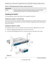
Managed Layer 2 Switch with 2 Gigabit Ethernet Ports FSM726E Hardware Installation Guide Table 2-1. Site Requirements for Switch Location (continued) Requirements Cabling Route the cable to avoid sources of electrical noise such as radio transmitters, broadcast amplifiers, power lines, and fluorescent lighting fixtures. Installing the Switch You can install the switch on a flat surface or in a standard 19-inch rack. Installing the Switch on a Flat Surface The switch ships with four self-adhesive rubber footpads. Stick one rubber footpad on each of the four concave spaces on the bottom of the switch. The rubber footpads cushion the switch against shock and vibrations. Installing the Switch in a Rack To install the switch in a rack, you need the 19-inch rack-mount kit supplied with your switch. 1. Attach the supplied mounting brackets to the side of the switch. 2. Use the provided Phillips head screws to fasten the brackets to the sides of the switch: Figure 2-1 2-4 v1.0, November 2008 Hardware Installation
-
 1
1 -
2
-
3
-
4
-
5
-
6
-
7
-
8
-
9
-
10
-
11
-
12
-
13
-
14
-
 15
15 -
 16
16 -
 17
17 -
 18
18 -
 19
19 -
 20
20 -
 21
21 -
 22
22 -
 23
23 -
 24
24 -
 25
25 -
26
-
27
-
28
-
29
-
30
 |
 |
