Netgear GS524T GS524T Reference Manual - Page 14
Rear Panel - fan
 |
UPC - 606449022803
View all Netgear GS524T manuals
Add to My Manuals
Save this manual to your list of manuals |
Page 14 highlights
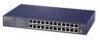
LEDs Table 2-1 describes the activity of the LEDs. Table 2-1. LED Descriptions Label Color Activity Description Power Green On Off Power is supplied to the switch. Power is disconnected. FDX/COL Green Yellow On Off Blinking The port is operating in full-duplex mode. The port is operating in half-duplex mode. Data collisions are occurring on the port. In a full-duplex environment, there is no collision. In a half-duplex environment, some collisions are normal. Activity/ 10M Green Blinking On Off Packet transmission or reception is occurring on the port. A valid 10 Mbps link is established on the port. No Activity on the port. 1000M Green On Off A valid 1000 Mbps link is established on the port. A link is not established on the port. 100M Green On Off A valid 100 Mbps link is established on the port. A link is not established on the port. Rear Panel As illustrated in Figure 2-5, the rear panel of the Model GS524T switch has fans for cooling and a standard AC Power Receptacle for the supplied power cord. Fans AC power Receptacle 100-240 VAC 50-60 Hz Figure 2-5. Rear Panel of the Model GS524T Switch physical description 2-4
-
 1
1 -
2
-
3
-
4
-
5
-
6
-
7
-
8
-
 9
9 -
 10
10 -
 11
11 -
 12
12 -
 13
13 -
 14
14 -
 15
15 -
 16
16 -
 17
17 -
 18
18 -
 19
19 -
20
-
21
-
22
-
23
-
24
-
25
-
26
-
27
-
28
-
29
-
30
-
31
-
32
-
33
-
34
 |
 |
