Netgear GS748TS GS7xxTS Hardware manual
Netgear GS748TS - ProSafe 48 Port Gigabit Stackable Smart Switch Manual
 |
UPC - 606449049480
View all Netgear GS748TS manuals
Add to My Manuals
Save this manual to your list of manuals |
Netgear GS748TS manual content summary:
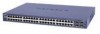
- Netgear GS748TS | GS7xxTS Hardware manual - Page 1
GS700TS (724TS, 748TS) Series Hardware Installation Guide NETGEAR, Inc. 4500 Great America Parkway Santa Clara, CA 95054 USA 202-10332-01 November 2007 - Netgear GS748TS | GS7xxTS Hardware manual - Page 2
software upgrades. NETGEAR, INC. Support Information Phone: 1-888-NETGEAR, for US & Canada only. For other countries, see your Support information card. E-mail: [email protected] North American NETGEAR website: http://www.netgear.com Trademarks NETGEAR, the NETGEAR instructions das Smart Switch gem - Netgear GS748TS | GS7xxTS Hardware manual - Page 3
with any other antenna or transmitter. FCC Declaration Of Conformity We NETGEAR, Inc., 4500 Great America Parkway, Santa Clara, CA 95054, declare under our sole responsibility that the model GS700TS Smart Switch with Gigabit Ports complies with Part 15 of FCC Rules. Operation is subject to - Netgear GS748TS | GS7xxTS Hardware manual - Page 4
, unless expressly approved by NETGEAR, Inc., could void the user's right to operate the equipment. D Canadian Department of Communications Radio Interference Regulations This digital apparatus (GS700TS Smart Switch with Gigabit Ports) does not exceed the Class B limits for radio-noise emissions - Netgear GS748TS | GS7xxTS Hardware manual - Page 5
a Device 2-33 Step 7: Applying AC Power 2-34 Step 8: Managing the Switch through a Web Browser or the PC Utility for Initial Configuration ...2-35 Chapter 3 Physical Description Front and Back Panel Configuration 3-19 GS724TS Front and Back Panels 3-19 GS748TS Front and Back Panels 3-20 v v1 - Netgear GS748TS | GS7xxTS Hardware manual - Page 6
-45 Ports ...3-23 SFP GBIC Module 3-24 Factory Defaults Button 3-24 Appendix A Troubleshooting Troubleshooting Chart A-1 Additional Troubleshooting Suggestions A-2 Network Adapter Cards A-2 Configuration ...A-2 Switch Integrity ...A-2 Auto-negotiation ...A-3 Appendix B Technical Specifications - Netgear GS748TS | GS7xxTS Hardware manual - Page 7
About This Guide Congratulations on the purchase of the NETGEAR Smart Switch. The NETGEAR® GS700TS Installation Manual describes how to install, configure and troubleshoot the smart switch. The information in this manual is intended for readers with intermediate computer and Internet skills. - Netgear GS748TS | GS7xxTS Hardware manual - Page 8
GS700TS Hardware Installation Guide • Scope. This manual is written for the GS700TS according to these specifications: Product Version Manual Publication Date GS700TS Smart Switch November 2007 Note: Product updates are available on the NETGEAR, Inc. web site at http://kbserver.netgear.com/main. - Netgear GS748TS | GS7xxTS Hardware manual - Page 9
GS700TS Hardware Installation Guide - Click the print icon in the upper left of the window. Tip: If your printer supports printing two pages on a single sheet of paper, you can save paper and printer ink by selecting this feature. • Printing the Full Manual - Use the Complete PDF Manual link at the - Netgear GS748TS | GS7xxTS Hardware manual - Page 10
Contents Overview This Installation Guide is for the following NETGEAR Smart Switches: • GS724TS - This product offers support for 24 ports of 10/100/1000 BaseT of which four are Combo ports with four additional SFP combo fiber ports. • GS748TS - This product offers support for 48 ports of 10/100 - Netgear GS748TS | GS7xxTS Hardware manual - Page 11
, VLAN for traffic control, port trunking for increased bandwidth, and Class of Service (CoS) for traffic prioritization. These features provide better understanding and control of the network. Initial discovery of the switch on the network requires the SmartWizard Discovery program, a utility that - Netgear GS748TS | GS7xxTS Hardware manual - Page 12
Installation Guide Figure 1-1 Switch Features The following list identifies the key features of the NETGEAR Smart Switch. • 24/48 RJ-45 10/100/1000M auto-sensing Giga switching ports. • Four Small Form-factor Pluggable (SFP) GBIC slots, which function as combo ports. Combo ports are single ports - Netgear GS748TS | GS7xxTS Hardware manual - Page 13
to minimize packet loss/frame drops. • Half-duplex back-pressure control. • Per port LEDs, System LEDs. • Internal power supply. • Standard 1U high, rack mountable19"chassis. • Fan speed control supported (optional). Stacking Stacking provides multiple switch management through a single point - Netgear GS748TS | GS7xxTS Hardware manual - Page 14
same software version. A device can operate in one of the following modes: • Stand-alone - The unit runs as a general switch and does not run the stacking application. • Master Unit - Manages the Stack and is responsible for the configuration. • Master-Backup - Runs as a slave unit and monitors the - Netgear GS748TS | GS7xxTS Hardware manual - Page 15
contains the following: • NETGEAR Smart Switch • Rubber footpads for tabletop installation • Power cord • Rack-mount Kit for installing the switch in a 19-inch rack • Installation Guide • Smart Switch Resource CD with SmartWizard Discovery and User's manual • Warranty/Support Information Card If any - Netgear GS748TS | GS7xxTS Hardware manual - Page 16
your NETGEAR Smart Switch. Switch installation involves the following steps: Step 1: Preparing the Site Step 2: Installing the Switch Step 3: Checking the Installation Step 4: Connecting Devices to the Switch Step 5: Installing an SFP GBIC Module Step 6: Installing a Device Step 7: Applying AC Power - Netgear GS748TS | GS7xxTS Hardware manual - Page 17
Hardware Installation Guide Table 2-1. Site Requirements Characteristics Requirements Power source Environmental Provide a power source within 6 feet (1.8 meters) of the installation location. Power specifications for the switch are shown in Appendix A Appendix A "Troubleshooting". Ensure the - Netgear GS748TS | GS7xxTS Hardware manual - Page 18
the Installation Before applying power perform the following: • Inspect the equipment thoroughly. • Verify that all cables are installed correctly. • Check cable routing to make sure cables are not damaged or creating a safety hazard. • Ensure all equipment is mounted properly and securely. 2-31 - Netgear GS748TS | GS7xxTS Hardware manual - Page 19
. Note: Ethernet specifications limit the cable length between the switch and the attached device to 100 m (328 ft.). Step 5: Installing an SFP GBIC Module The following procedure describes how to install an SFP Gigabit Ethernet module in the switch's Gigabit module bay. Standard SFP GBIC modules - Netgear GS748TS | GS7xxTS Hardware manual - Page 20
Guide 2. Press firmly to ensure the module seats into the connector Figure 2-3 Step 6: Installing a Device The device can operate as part of a stack. The HX stacking ports on the back of the device are used for connecting the devices in a stack. There are two stacking topologies supported - Netgear GS748TS | GS7xxTS Hardware manual - Page 21
are configured through automatic discovery. Manually changing the stacking configuration is through switch web page once the device has been booted and is operational. For more information on stacking see the NETGEAR Smart Switch User Guide. Step 7: Applying AC Power NETGEAR Smart Switch does - Netgear GS748TS | GS7xxTS Hardware manual - Page 22
a Web browser or a utility program called SmartWizard Discovery. For more information about managing the switch, see the Software Manual on the Smart Switch Resource CD. Note: When the device powers up, there is a default IP address already configured on the device. The default IP address is 192.168 - Netgear GS748TS | GS7xxTS Hardware manual - Page 23
Front and Back Panels • GS748TS Front and Back Panels • LED Designations • Device Hardware Interfaces Front and Back Panel Configuration GS724TS Front and Back Panels The NETGEAR GS724TS Smart Switch is a 24-Port 10/100/1000 + 4-Port SFP Combo port switch, with each RJ45 ports capable of sensing the - Netgear GS748TS | GS7xxTS Hardware manual - Page 24
receptacle for accommodating the supplied power cord. • Two 19 pin HX stacking ports for full-duplex stacking linking. GS748TS Front and Back Panels The NETGEAR GS748TS Smart Switch is a 48-Port 10/100/1000 + 4-Port SFP Combo port smart stackable switch, with each RJ45 ports capable of sensing the - Netgear GS748TS | GS7xxTS Hardware manual - Page 25
Installation Guide Figure 3-2 illustrates the NETGEAR GS748TS Smart Switch back panel: Figure 3-4 The back panel contains the following: • A 100-240VAC/50-60 Hz universal input, which is a standard AC power receptacle for accommodating the supplied power cord. • Two 19 pin HX stacking ports for - Netgear GS748TS | GS7xxTS Hardware manual - Page 26
master unit in a stack of switches. The Stack Master LED is lit if there is an active stack link, and the unit is in stack mode. Indicates the Up stacking port LED designations • Off - Indicates the Up stacking port link is down. • Solid Green - Indicates the Up stacking port link is up. • Flashing - Netgear GS748TS | GS7xxTS Hardware manual - Page 27
- The fan is not operating normally. Device Hardware Interfaces This section provides information for the following hardware interfaces: • RJ-45 Ports • SFP GBIC Module • Factory Defaults Button RJ-45 Ports RJ-45ports are auto-sensing ports. When inserting a cable into an RJ-45 port, the switch - Netgear GS748TS | GS7xxTS Hardware manual - Page 28
a standard SFP GBIC module. Factory Defaults Button The Smart Switch has a Factory default button to enable clearing the current configuration and returning the device back to the factory settings. This removes all settings, including the password, VLAN settings and port configurations. 3-24 - Netgear GS748TS | GS7xxTS Hardware manual - Page 29
problems. Table A-1. Troubleshooting Chart Symptom Cause Solution Power LED is off. No power is received. Check the power cord connections for the switch at the switch and the connected device. Ensure all cables are used correctly and comply with the Ethernet specifications. Link LED - Netgear GS748TS | GS7xxTS Hardware manual - Page 30
do not exceed the Ethernet limitations. Switch Integrity If required, verify the integrity of the switch by resetting the switch. To reset the switch, disconnect the AC power from the switch and then reconnect AC source. If the problem continues, contact NETGEAR technical support. In North America - Netgear GS748TS | GS7xxTS Hardware manual - Page 31
not support auto negotiation, the switch only determines the speed correctly and the duplex mode defaults to half-duplex. The gigabit port on the Gigabit module negotiates speed, duplex mode, and flow control, provided that the attached device supports auto-negotiation. Troubleshooting A-3 v1 - Netgear GS748TS | GS7xxTS Hardware manual - Page 32
). 4 RJ-45 connectors for 10Base-T ,100Base-TX and 1000Base-T, shared with SFP slots. Four Small Form-factor Pluggable (SFP) slots for SFP module. LEDs Per port (Gigabit): Link/Activity, Speed, Stack (for stacking-enabled ports) Per device: Power, Stack Master, Unit Number B-1 v1.0, November 2007 - Netgear GS748TS | GS7xxTS Hardware manual - Page 33
Gbps (for GS724TS) / 116 Gbps (for GS748TS) Stacking Port Bandwidth: 20 Gbps Address database size: 4K media access control (MAC) addresses per system Mean Time Between Failure (MTBF): 167,355 hours for GS724TS, 125,566 hours for GS748TS Power Supply Power Consumption: 35.1W for GS724TS, 78.36W for - Netgear GS748TS | GS7xxTS Hardware manual - Page 34
Immunity EN 55022 (CISPR 22), Class A Safety CE mark, commercial UL listed (UL 1950) / CUL IEC950 / EN60950 Modules AGM731F 1000Base-SX SFP GBIC for multimode fiber AGM732F 1000Base-LX SFP GBIC for single mode fiber AGM733 1000Base-LZ GBIC for long haul single mode fiber B-3 Technical - Netgear GS748TS | GS7xxTS Hardware manual - Page 35
Service 1-2 Combo Port 2-10 Combo Ports 1-2 Connecting Devices to the Switch 4-16 Copper 1-1 Crossover 2-9 D Default IP Address 4-18 Default Reset Button 2-5, 2-7 Device Hardware Interfaces 2-9 Duplex Mode 2-9 E Example of Desktop Switching 3-12 F Factory Default Button 2-10 Factory Defaults 2-5 Fan - Netgear GS748TS | GS7xxTS Hardware manual - Page 36
-mount Kit 1-4, 4-14 Reset Button 2-5, 2-7 RJ-45 1-2 RJ-45 Ports 2-9 Rubber Footpad 4-14 Rubber footpads 1-4 S SFP GBIC Module 2-10 SFP Link/ACT LED 2-8 SFP Module Bay 4-17 Site Requirements 4-13 Small Form-factor Pluggable (SFP) 1-2 Smart Switch Resource CD 1-4 SmartWizard Discovery 1-2 Straight - Netgear GS748TS | GS7xxTS Hardware manual - Page 37
User's Manual 1-4 UTP 4-16 V Ventilation 4-14 VLAN 1-1 W Warranty 1-4 Web-based Graphical User Interface 1-1 v1.0, November 2007 Index-3 - Netgear GS748TS | GS7xxTS Hardware manual - Page 38
v1.0, November 2007 Index-4
-
 1
1 -
 2
2 -
 3
3 -
 4
4 -
 5
5 -
 6
6 -
 7
7 -
8
-
9
-
10
-
11
-
12
-
13
-
14
-
15
-
16
-
17
-
18
-
19
-
20
-
21
-
22
-
23
-
24
-
25
-
26
-
27
-
28
-
29
-
30
-
31
-
32
-
33
-
34
-
35
-
36
-
37
-
38
 |
 |
202-10332-01
November 2007
NETGEAR
, Inc.
4500 Great America Parkway
Santa Clara, CA 95054 USA
GS700TS (724TS, 748TS)
Series Hardware
Installation Guide