Netgear GS748TS GS7xxTS Hardware manual - Page 25
LED Designations, illustrates the NETGEAR GS748TS Smart Switch back panel - stacking guide
 |
UPC - 606449049480
View all Netgear GS748TS manuals
Add to My Manuals
Save this manual to your list of manuals |
Page 25 highlights
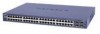
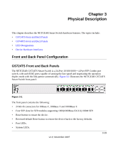
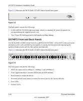
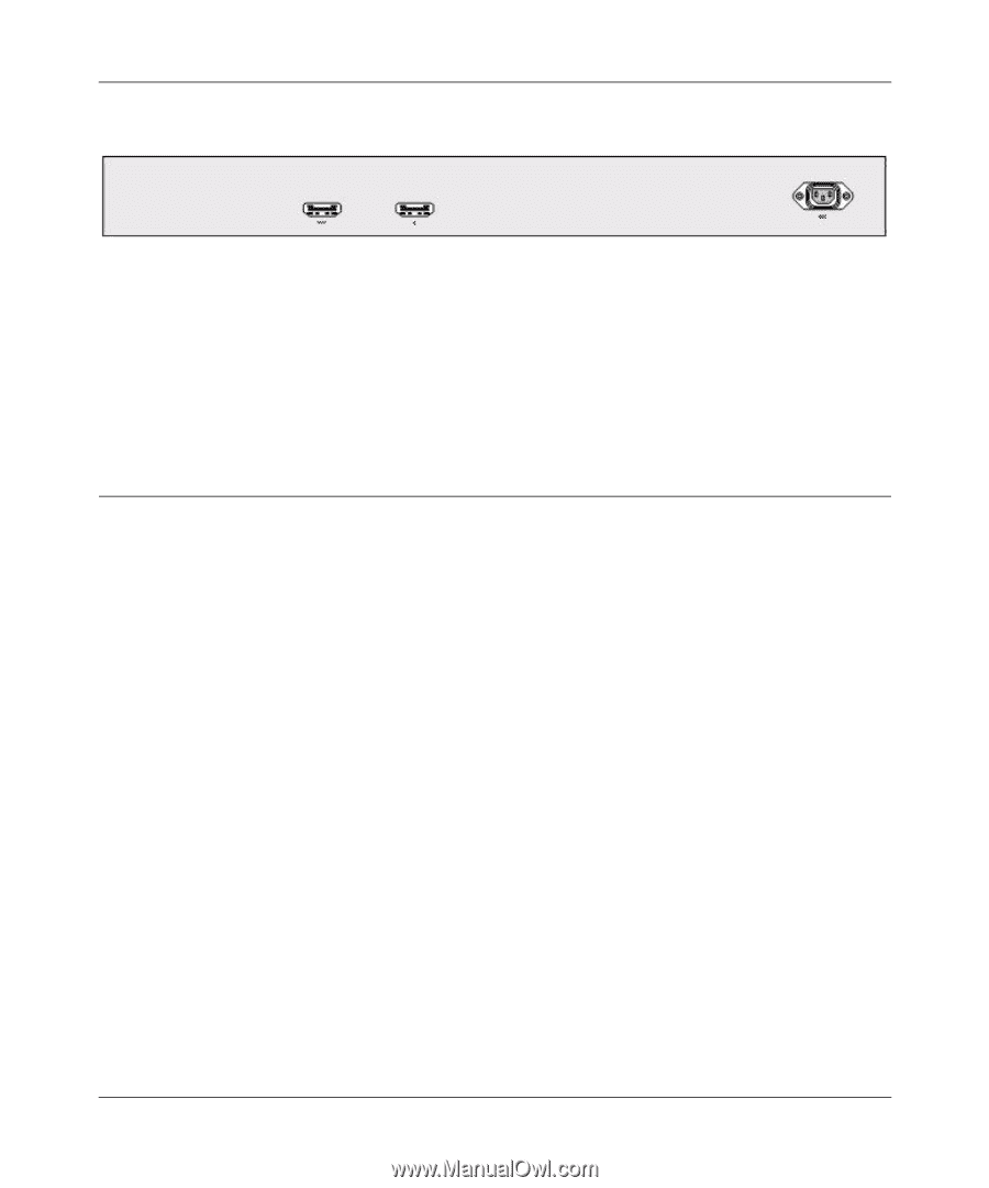
GS700TS Hardware Installation Guide Figure 3-2 illustrates the NETGEAR GS748TS Smart Switch back panel: Figure 3-4 The back panel contains the following: • A 100-240VAC/50-60 Hz universal input, which is a standard AC power receptacle for accommodating the supplied power cord. • Two 19 pin HX stacking ports for full-duplex stacking linking. LED Designations This section provides an explanation for the following LED types: • Port LEDs • System LEDs Physical Description v1.0, November 2007 3-21
-
 1
1 -
2
-
3
-
4
-
5
-
6
-
7
-
8
-
9
-
10
-
11
-
12
-
13
-
14
-
15
-
16
-
17
-
18
-
19
-
 20
20 -
 21
21 -
 22
22 -
 23
23 -
 24
24 -
 25
25 -
 26
26 -
 27
27 -
 28
28 -
 29
29 -
 30
30 -
31
-
32
-
33
-
34
-
35
-
36
-
37
-
38
 |
 |
GS700TS Hardware Installation Guide
Physical Description
3-21
v1.0, November 2007
Figure 3-2
illustrates the NETGEAR GS748TS Smart Switch back panel:
The back panel contains the following:
•
A 100-240VAC/50-60 Hz universal input, which is a standard AC power receptacle for
accommodating the supplied power cord.
•
Two 19 pin HX stacking ports for full-duplex stacking linking.
LED Designations
This section provides an explanation for the following LED types:
•
Port LEDs
•
System LEDs
Figure 3-4