Netgear MBR624GU MBR624GU User Manual - Page 17
Back Panel, Table 1-1., LED Descriptions, continued - 3g
 |
UPC - 606449061215
View all Netgear MBR624GU manuals
Add to My Manuals
Save this manual to your list of manuals |
Page 17 highlights
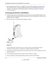
3G Broadband Wireless Router MBR624GU User Manual Table 1-1. LED Descriptions (continued) 4. USB 5. Internet Solid green Blinking green Off Solid green Blinking green Red Off The wireless USB modem is attached to the USB port. Data is being transmitted or received. No link is detected on this port, or the USB modem is powered off. The router is connected to the Internet. The router is connected to the Internet and traffic is passing through the device. No Internet connection. The router is powered off. Back Panel 1 5 23 4 4 Figure 1-2 The router ports are color-coded to distinguish your Internet port from the other four ports that connect to the wired computer(s) on your LAN. The rear panel contains the following elements: 1. Wireless antenna 2. AC power adapter input 3. Power switch 4. USB port for connecting a wireless USB modem (sold separately). 5. Four local Ethernet RJ-45 LAN ports for connecting the router to the local computers Installing Your Router 1-3 v1.1, March 2009
-
 1
1 -
2
-
3
-
4
-
5
-
6
-
7
-
8
-
9
-
10
-
11
-
 12
12 -
 13
13 -
 14
14 -
 15
15 -
 16
16 -
 17
17 -
 18
18 -
 19
19 -
 20
20 -
 21
21 -
 22
22 -
23
-
24
-
25
-
26
-
27
-
28
-
29
-
30
-
31
-
32
-
33
-
34
-
35
-
36
-
37
-
38
-
39
-
40
-
41
-
42
-
43
-
44
-
45
-
46
-
47
-
48
-
49
-
50
-
51
-
52
-
53
-
54
-
55
-
56
-
57
-
58
-
59
-
60
-
61
-
62
-
63
-
64
-
65
-
66
-
67
-
68
-
69
-
70
-
71
-
72
-
73
-
74
-
75
-
76
-
77
-
78
-
79
-
80
-
81
-
82
-
83
-
84
-
85
-
86
-
87
-
88
-
89
-
90
-
91
-
92
-
93
-
94
-
95
-
96
-
97
-
98
-
99
-
100
-
101
-
102
-
103
-
104
-
105
-
106
 |
 |
