Netgear WB7520 User Manual - Page 79
Manually Add and Manage Antennas on a Floor Map for an RF Plan, Step 7
 |
View all Netgear WB7520 manuals
Add to My Manuals
Save this manual to your list of manuals |
Page 79 highlights
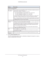
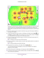
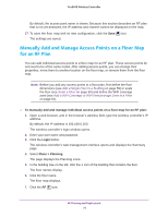
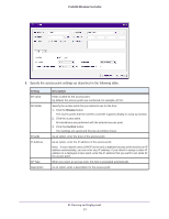
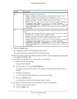
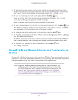
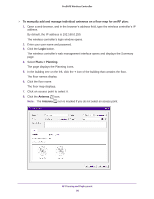
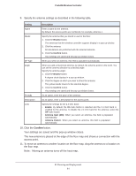
ProSAFE Wireless Controller 13. To add another access point to the floor map, change the properties for another access point, move another access point on the floor map, remove another access point from the floor map, or perform a combination of these tasks, repeat Step 7 through Step 12. 14. To turn the heat map on or off, on the right, click the HeatMap icon. If you turn on the heat map, the heat map is generated and displays. Use the color information on the right as guidance for WiFi coverage. Note: Adding or removing access points changes the heat map. 15. To switch the heat map to the 2.4 GHz or 5 GHz band, on the right, click the Band icon. The Band icon displays 2.4G if the heat map for the 2.4 GHz band is shown. The Band icon displays 5G if the heat map for the 5 GHz band is shown. 16. To show the map with or without grid, on the right side, click the Grid icon. 17. To show the access points by model or without a label, on the right side, click the Label icon and select your preference. By default, the access point name is shown. Because this section describes an RF plan that is not yet deployed, the IP address and channel cannot be displayed on the map. 18. To save the floor map with its new configuration, click the Save The settings are saved. icon. Manually Add and Manage Antennas on a Floor Map for an RF Plan You can add individual antennas to a floor map for an RF plan. These antennas do not need to be of the same model. After adding antennas, you can change their properties, move them to another location on the floor map, or remove them from the floor map. Note: Antennas are associated with access points. Therefore, before you add antennas to a floor plan, first add access points to the floor plan. For more information about adding access points to a floor plan, see Use the WiFi Auto Planning Advisor to Generate an RF Plan for a Floor on page 70 and Manually Add and Manage Access Points on a Floor Map for an RF Plan on page 76. RF Planning and Deployment 79
-
 1
1 -
2
-
3
-
4
-
5
-
6
-
7
-
8
-
9
-
10
-
11
-
12
-
13
-
14
-
15
-
16
-
17
-
18
-
19
-
20
-
21
-
22
-
23
-
24
-
25
-
26
-
27
-
28
-
29
-
30
-
31
-
32
-
33
-
34
-
35
-
36
-
37
-
38
-
39
-
40
-
41
-
42
-
43
-
44
-
45
-
46
-
47
-
48
-
49
-
50
-
51
-
52
-
53
-
54
-
55
-
56
-
57
-
58
-
59
-
60
-
61
-
62
-
63
-
64
-
65
-
66
-
67
-
68
-
69
-
70
-
71
-
72
-
73
-
 74
74 -
 75
75 -
 76
76 -
 77
77 -
 78
78 -
 79
79 -
 80
80 -
 81
81 -
 82
82 -
 83
83 -
 84
84 -
85
-
86
-
87
-
88
-
89
-
90
-
91
-
92
-
93
-
94
-
95
-
96
-
97
-
98
-
99
-
100
-
101
-
102
-
103
-
104
-
105
-
106
-
107
-
108
-
109
-
110
-
111
-
112
-
113
-
114
-
115
-
116
-
117
-
118
-
119
-
120
-
121
-
122
-
123
-
124
-
125
-
126
-
127
-
128
-
129
-
130
-
131
-
132
-
133
-
134
-
135
-
136
-
137
-
138
-
139
-
140
-
141
-
142
-
143
-
144
-
145
-
146
-
147
-
148
-
149
-
150
-
151
-
152
-
153
-
154
-
155
-
156
-
157
-
158
-
159
-
160
-
161
-
162
-
163
-
164
-
165
-
166
-
167
-
168
-
169
-
170
-
171
-
172
-
173
-
174
-
175
-
176
-
177
-
178
-
179
-
180
-
181
-
182
-
183
-
184
-
185
-
186
-
187
-
188
-
189
-
190
-
191
-
192
-
193
-
194
-
195
-
196
-
197
-
198
-
199
-
200
-
201
-
202
-
203
-
204
-
205
-
206
-
207
-
208
-
209
-
210
-
211
-
212
-
213
-
214
-
215
-
216
-
217
-
218
-
219
-
220
-
221
-
222
-
223
-
224
-
225
-
226
-
227
-
228
-
229
-
230
-
231
-
232
-
233
-
234
-
235
-
236
-
237
-
238
-
239
-
240
-
241
-
242
-
243
-
244
-
245
-
246
-
247
-
248
-
249
-
250
-
251
-
252
-
253
-
254
-
255
-
256
-
257
-
258
-
259
-
260
-
261
-
262
-
263
-
264
-
265
-
266
-
267
-
268
-
269
-
270
-
271
-
272
-
273
-
274
-
275
-
276
-
277
-
278
-
279
-
280
-
281
-
282
-
283
-
284
-
285
-
286
-
287
-
288
-
289
-
290
-
291
-
292
-
293
-
294
-
295
-
296
-
297
-
298
-
299
-
300
-
301
-
302
-
303
-
304
-
305
-
306
-
307
-
308
-
309
-
310
-
311
-
312
-
313
-
314
-
315
-
316
-
317
-
318
-
319
-
320
-
321
-
322
-
323
-
324
-
325
-
326
-
327
-
328
-
329
-
330
-
331
-
332
-
333
-
334
-
335
-
336
-
337
-
338
-
339
-
340
-
341
-
342
-
343
-
344
-
345
-
346
-
347
-
348
-
349
-
350
-
351
-
352
-
353
-
354
-
355
-
356
-
357
-
358
-
359
-
360
-
361
-
362
-
363
-
364
-
365
-
366
-
367
-
368
-
369
-
370
-
371
-
372
-
373
-
374
-
375
-
376
-
377
-
378
-
379
-
380
-
381
-
382
-
383
-
384
-
385
-
386
-
387
-
388
-
389
-
390
-
391
-
392
-
393
-
394
-
395
-
396
-
397
-
398
 |
 |
