Netgear XSM4348CS Hardware Installation Guide - Page 39
Table 3. LEDs of the full 10G models with RJ45/SFP+ combo ports, Hardware Installation Guide
 |
View all Netgear XSM4348CS manuals
Add to My Manuals
Save this manual to your list of manuals |
Page 39 highlights
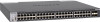
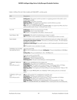
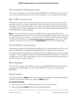
M4300 Intelligent Edge Series Fully Managed Stackable Switches Table 3. LEDs of the full 10G models with RJ45/SFP+ combo ports LED Designation Power LED Solid green. The power module is present, is supplying power to the switch, and is functioning normally. Solid yellow. The switch is booting. Blinking yellow. The system boot-up failed or another failure occurred. Off. Power is not supplied to the switch. Note: Because models M4300-48X and M4300-48XF can support two PSUs, the front panel provides both a Power 1 LED and Power 2 LED. Fan LED Solid green. The fans are functioning normally. Solid yellow. One or more fans failed. Off. Power is not supplied to the switch. The fans are off. Stack Master LED Solid green. The switch is functioning as a master in a stack. Off. The switch is not a member of a stack or is functioning as a slave in a stack. Stack ID LED The Stack LED contains segments that can indicate the stack unit number of the switch: Solid green indicating a number. The switch is a member of a stack. The LED displays the stack unit number. Solid green indicating E. The switch functions in ECO mode with all port LEDs turned off. Off. The switch is not a member of a stack. OOB Ethernet port LEDs (two LEDs per port) Left side speed LED: Off. No link is established on the port. Solid green. The port established a 1000 Mbps link. Solid yellow. The port established a 10 or 100 Mbps link. Right side activity and link LED: Off. No link is established on the port. Solid green. The port established a link. Blinking green. The port is transmitting or receiving packets. 10GBASE-T RJ45 port LED (one LED per port) Off. No link is established on the copper port. Solid green. The copper port established a 10 Gbps link. Blinking green. The copper port is transmitting or receiving packets at 10 Gbps. Solid yellow. The copper port established a 1 Gbps or 100 Mbps link. Blinking yellow. The copper port is transmitting or receiving packets at 1 Gbps or 100 Mbps. Note: On model M4300-24XF, the 10GBASE-T RJ45 combo ports are on the back panel. 10GBASE-X SFP+ port LED (one LED per port) Off. No SFP module link is established on the fiber port. Solid green. The fiber port established a 10 Gbps link. Blinking green. The fiber port is transmitting or receiving packets at 10 Gbps. Solid yellow. The fiber port established a 1 Gbps link. Blinking yellow. The fiber port is transmitting or receiving packets at 1 Gbps. Note: On model M4300-24X, the 10GBASE-X SFP+ combo ports are on the back panel. Hardware Overview 39 Hardware Installation Guide
-
 1
1 -
2
-
3
-
4
-
5
-
6
-
7
-
8
-
9
-
10
-
11
-
12
-
13
-
14
-
15
-
16
-
17
-
18
-
19
-
20
-
21
-
22
-
23
-
24
-
25
-
26
-
27
-
28
-
29
-
30
-
31
-
32
-
33
-
 34
34 -
 35
35 -
 36
36 -
 37
37 -
 38
38 -
 39
39 -
 40
40 -
 41
41 -
 42
42 -
 43
43 -
 44
44 -
45
-
46
-
47
-
48
-
49
-
50
-
51
-
52
-
53
-
54
-
55
-
56
-
57
-
58
-
59
-
60
-
61
-
62
-
63
-
64
-
65
-
66
-
67
-
68
-
69
 |
 |
