NordicTrack E 9.0 Elliptical English Manual - Page 28
Next, locate the Reed Switch 38. Turn the left Crank
 |
View all NordicTrack E 9.0 Elliptical manuals
Add to My Manuals
Save this manual to your list of manuals |
Page 28 highlights
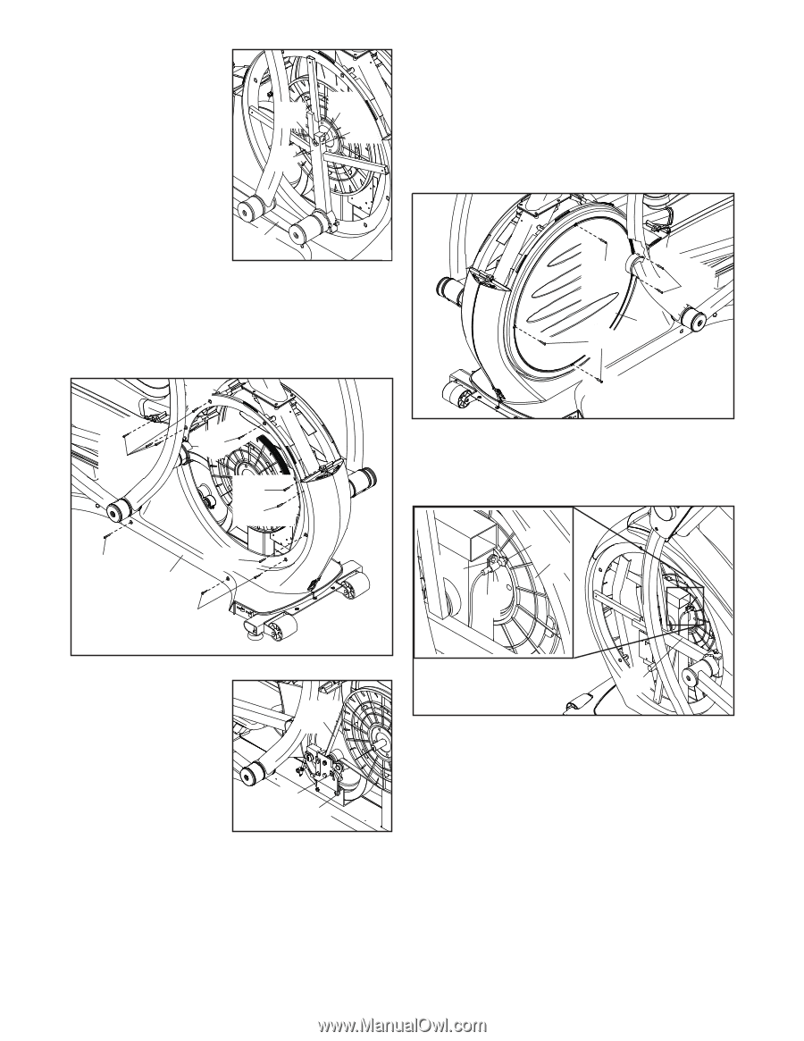
Loosen the M6 x 12mm Hex Screw (85) and the M10 x 58mm Hex Bolt (86). Then, remove the right Crank Arm (20). Gently move the right Crank Arm and the Right Roller Arm (45) out of the way. Do not misplace the Key (78) while removing the Crank Arm. 86 78 85 20 45 Next, remove all the M4 x 16mm Screws (104) and all the M4 x 22mm Screws (127) from the Right Front Shield (74); note which size of screw you remove from each hole. Then, gently remove the Right Front Shield. HOW TO ADJUST THE REED SWITCH If the console does not display correct feedback, the reed switch should be adjusted. To adjust the reed switch, first remove all the M4 x 16mm Screws (104) from the left Disc (71). Then, gently remove the left Disc. 104 104 71 104 104 127 127 104 104 127 74 104 Next, locate the Reed Switch (38). Turn the left Crank Arm (20) until one of the Magnets (43) on the Pulley (19) is aligned with the Reed Switch. 104 38 43 19 Locate and loosen the Idler Screw (101). Next, tighten the Belt Adjustment Screw (88) until the Drive Belt (113) is tight. Then, retighten the Idler Screw. 113 101 88 Reattach the right front shield, the right crank arm, the right disc, the front stabilizer cover, the shield cover, and the lower upright cover. 20 Loosen, but do not remove, the M4 x 16mm Screw (104). Slide the Reed Switch (38) slightly closer to or away from the Magnet (43). Then, retighten the Screw. Turn the left Crank Arm (20) for a moment. Repeat these actions until the console displays correct feedback. Then, reattach the left disc. 28
-
 1
1 -
2
-
3
-
4
-
5
-
6
-
7
-
8
-
9
-
10
-
11
-
12
-
13
-
14
-
15
-
16
-
17
-
18
-
19
-
20
-
21
-
22
-
 23
23 -
 24
24 -
 25
25 -
 26
26 -
 27
27 -
 28
28 -
 29
29 -
 30
30 -
 31
31 -
 32
32 -
 33
33 -
34
-
35
-
36
 |
 |