NordicTrack Elite 7700 Treadmill English Manual - Page 13
If You Do Not Connect
 |
View all NordicTrack Elite 7700 Treadmill manuals
Add to My Manuals
Save this manual to your list of manuals |
Page 13 highlights
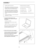
8. IMPORTANT: To avoid damaging the Pulse Crossbar (80), do not use power tools, and do 8 2 6 not overtighten the #10 x 3/4" Screws (6) or the 5/16" x 2" Screws (2). 8 Orient the Pulse Crossbar (80) as shown. Attach the Pulse Crossbar with two of the 5/16" x 2" Screws (2) that you removed in step 3, two 5/16" 2 Star Washers (8), and two #10 x 3/4" Screws (6). Start all four Screws, and then tighten them. Then, tighten the other two 5/16" x 2" Screws (2). 80 2 6 8 2 9. With the help of a second person, hold the console assembly (D) near the Handrails (74). See the inset drawing. Connect the Upright Wire (83) to the console wire (F). The connectors should slide together easily and snap into place. If they do not, turn one connector and try again. IF YOU DO NOT CONNECT THE CONNECTORS PROPERLY, THE CONSOLE MAY BECOME DAMAGED WHEN YOU TURN ON THE POWER. Next, connect the two fan wires (B, G). Then, remove any wire ties from the Upright Wire (83) and the fan wires. Connect the two coaxial cables on the other side (not shown). Insert the excess cable and fan wire into the Upright (84). 9 D F 83 74 G B 84 F 83 13
-
 1
1 -
2
-
3
-
4
-
5
-
6
-
7
-
 8
8 -
 9
9 -
 10
10 -
 11
11 -
 12
12 -
 13
13 -
 14
14 -
 15
15 -
 16
16 -
 17
17 -
 18
18 -
19
-
20
-
21
-
22
-
23
-
24
-
25
-
26
-
27
-
28
-
29
-
30
-
31
-
32
-
33
-
34
-
35
-
36
-
37
-
38
-
39
-
40
-
41
-
42
-
43
-
44
-
45
-
46
-
47
-
48
-
49
-
50
-
51
-
52
 |
 |
