Oki GL408e GL408e/GL412e RFID Kit Install Guide - Page 9
b., Insert the reader as, shown, a., Ports on the Reader, Subassembly., c.,
 |
View all Oki GL408e manuals
Add to My Manuals
Save this manual to your list of manuals |
Page 9 highlights
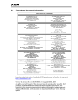
Assembling the Reader Module Parts required READER MOUNT SUBASSEMBLY, GL4xxe Tool(s) required #1 Phillips + screwdriver - 8 in. lb. 1. Plug the antenna cable into the port on the right side of the Reader Subassembly as indicated in Figure 4a. 2. Route the other end of the cable into the electronics section of the printer. The cable connects to the white connector on the printer's main PCB, near the moto. See Figure 4c. 3. Position the reader subassembly within the lower part of the print head area. while pulling any excess length of interface cable slack back into the electronics side of the printer. 4. Attach the reader subassembly to the printer with the supplied 4 screw (circled red in Figure 4b). 5. Tighten and torque the screw. 6. Close and latch the deck assembly. 7. Position the antenna handle above the printed orangecolored marker's location for testing. Note When installing the reader subassembly, make sure that the antenna or power/data cables are not crimped by any moving part within the mounting area. Antenna cable Figure 4a. Ports on the Reader Subassembly. Figure 4b. Insert the reader as shown Figure 4c. Insert the connector as shown 9
-
 1
1 -
2
-
3
-
 4
4 -
 5
5 -
 6
6 -
 7
7 -
 8
8 -
 9
9 -
 10
10 -
 11
11
 |
 |
