Oki ML490 Maintenance Manual - Page 98
Lamp Display
 |
View all Oki ML490 manuals
Add to My Manuals
Save this manual to your list of manuals |
Page 98 highlights
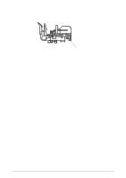
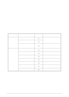
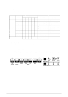
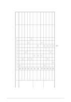
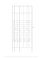
6.3 Lamp Display (1) Printer mode display Table 6.2 ALARM CATEGORY ALARM LED CONDITION ALARM SEL MENU 10CPI 15CPI CONTENTS TROUBLE SHOOTING Paper end alarm ON Paper change lever alarm ON OPERATOR ALARM Paper jam alarm ON Print Head thermal alarm OFF Space motor thermal alarm FATAL ALARM OFF BLINK 2 OFF OFF OFF OFF From, cut sheet or bottom paper end Set New paper. BLINK 1 OFF Change lever is set to TOP position while paper is already inserted from rear or bottom. Set the lever to specified position. Check rear sensor lever. Replace Control Board OFF BLINK 1 Cut sheet could not be ejected. Cut sheet could not be fed properly Remove the paper or check feed Mechanism Press SEL key. BLINK 1 Print head temperature exceeds 119¡C Wait until it is cooled. Replace P.H. or Control Board BLINK 1 Temperature of space motor exceeds specified value. It is recovered automatically Replace SP motor or Control Board OFF See Table 6.3 Hardware Alarm has occurred. See Table 6.3. Note: BLINK1 : 400ms ON, 400ms OFF BLINK2 : 200ms ON, 200ms OFF - : LED is kept in Current Condition (no change) (2) Fault alram display When the printer detects any of the various alarm states, the information is displayed as shown below on the operation panel. The alarm is specified by lamp combination of PRINT QUALITY and CHARACTER PITCH. (See Table 6.3 for details.) Figure 6-1 42114101 Rev.1 98 /
-
 1
1 -
2
-
3
-
4
-
5
-
6
-
7
-
8
-
9
-
10
-
11
-
12
-
13
-
14
-
15
-
16
-
17
-
18
-
19
-
20
-
21
-
22
-
23
-
24
-
25
-
26
-
27
-
28
-
29
-
30
-
31
-
32
-
33
-
34
-
35
-
36
-
37
-
38
-
39
-
40
-
41
-
42
-
43
-
44
-
45
-
46
-
47
-
48
-
49
-
50
-
51
-
52
-
53
-
54
-
55
-
56
-
57
-
58
-
59
-
60
-
61
-
62
-
63
-
64
-
65
-
66
-
67
-
68
-
69
-
70
-
71
-
72
-
73
-
74
-
75
-
76
-
77
-
78
-
79
-
80
-
81
-
82
-
83
-
84
-
85
-
86
-
87
-
88
-
89
-
90
-
91
-
92
-
 93
93 -
 94
94 -
 95
95 -
 96
96 -
 97
97 -
 98
98 -
 99
99 -
 100
100 -
 101
101 -
 102
102 -
 103
103 -
104
-
105
-
106
-
107
-
108
-
109
-
110
-
111
-
112
-
113
-
114
-
115
-
116
-
117
-
118
-
119
-
120
-
121
-
122
-
123
-
124
-
125
-
126
-
127
-
128
-
129
-
130
-
131
-
132
-
133
-
134
-
135
 |
 |
