Olympus 135291 P-440 Reference Manual (English) - Page 6
Identifying the Parts, Printer Body
 |
UPC - 050332135284
View all Olympus 135291 manuals
Add to My Manuals
Save this manual to your list of manuals |
Page 6 highlights
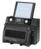
Identifying the Parts qPrinter Body Operation panel This is used when printing by inserting a card (xD-Picture Card/PC card) directly into the printer. (Refer to the section on the "Operation Panel" on page 7 for further details.) Printer cover This is opened when installing or replacing the ink cassette. Power (ON/OFF) switch Paper cassette compartment lid Dust cover The dust cover is opened when the paper cassette is inserted. Cover eject lever Paper output tray This is pulled out when printing. xD-Picture Card slot xD-Picture Card containing recorded pictures is inserted into this slot when printing directly from an xD-Picture Card. PC card eject button Paper discharge opening Paper is discharged from this This button is pressed to remove the PC card. opening after printing. PC card slot This slot is for inserting PC cards complying with PC standard ATA specifications (PCMCIA). Type II PC cards can be used. Use a PC card adapter or similar device when printing SmartMedia, CompactFlash or Memory Stick data. VIDEO OUT jack This jack is used to connect the printer to a VIDEO IN port on a TV monitor. USB connector This connector is used to connect a USB cable from a PC. AC power connector This connector is used to connect the power cord. 6
-
 1
1 -
 2
2 -
 3
3 -
 4
4 -
 5
5 -
 6
6 -
 7
7 -
 8
8 -
 9
9 -
 10
10 -
 11
11 -
 12
12 -
13
-
14
-
15
-
16
-
17
-
18
-
19
-
20
-
21
-
22
-
23
-
24
-
25
-
26
-
27
-
28
-
29
-
30
-
31
-
32
-
33
-
34
-
35
-
36
-
37
-
38
-
39
-
40
-
41
-
42
-
43
-
44
-
45
-
46
-
47
-
48
-
49
-
50
-
51
-
52
-
53
-
54
-
55
-
56
-
57
-
58
-
59
-
60
-
61
-
62
-
63
-
64
-
65
-
66
-
67
-
68
-
69
-
70
-
71
-
72
-
73
-
74
-
75
-
76
-
77
-
78
-
79
-
80
-
81
-
82
-
83
-
84
-
85
-
86
-
87
-
88
-
89
-
90
-
91
-
92
-
93
-
94
-
95
-
96
-
97
-
98
-
99
-
100
-
101
-
102
-
103
-
104
-
105
-
106
-
107
-
108
-
109
-
110
-
111
-
112
-
113
-
114
-
115
-
116
-
117
-
118
-
119
-
120
-
121
-
122
-
123
-
124
-
125
-
126
-
127
-
128
-
129
-
130
-
131
-
132
-
133
-
134
-
135
-
136
-
137
-
138
-
139
-
140
-
141
-
142
-
143
-
144
-
145
-
146
-
147
-
148
-
149
-
150
-
151
-
152
-
153
-
154
-
155
-
156
 |
 |
