Optoma GT1080DARBEE GT1080Darbee User Manual - Page 9
Product Overview, Note°
 |
View all Optoma GT1080DARBEE manuals
Add to My Manuals
Save this manual to your list of manuals |
Page 9 highlights
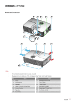
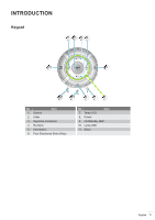
INTRODUCTION Product Overview 12 3 4 5 8 7 13 6 9 10 11 8 12 Note: ‡‡ ‡‡ Do not block projector inlet or outlet air vents. Keep a minimum distance of 20 cm between the "inlet" and "outlet" labels. No Item 1. Lens 2. IR Receiver 3. Keypad 4. Input / Output Connections 5. Power Socket 6. Speaker 7. Lens Cap No Item 8. Tilt-Adjustment Feet 9. Focus Ring 10. Lamp Cover 11. Ventilation (outlet) 12. KensingtonTM Lock Port 13. Ventilation (inlet) English 9
-
 1
1 -
2
-
3
-
 4
4 -
 5
5 -
 6
6 -
 7
7 -
 8
8 -
 9
9 -
 10
10 -
 11
11 -
 12
12 -
 13
13 -
 14
14 -
15
-
16
-
17
-
18
-
19
-
20
-
21
-
22
-
23
-
24
-
25
-
26
-
27
-
28
-
29
-
30
-
31
-
32
-
33
-
34
-
35
-
36
-
37
-
38
-
39
-
40
-
41
-
42
-
43
-
44
-
45
-
46
-
47
-
48
-
49
-
50
-
51
-
52
-
53
 |
 |

English
9
INTRODUCTION
Product Overview
4
3
1
6
2
5
7
8
9
10
11
13
12
8
Note°
±
Do not block projector inlet or outlet air vents.
±
Keep a minimum distance of 20 cm between the “inlet” and “outlet” labels.
No
Item
No
Item
1.
Lens
8.
Tilt-Adjustment Feet
2.
IR Receiver
9.
Focus Ring
3.
Keypad
10.
Lamp Cover
4.
Input / Output Connections
11.
Ventilation (outlet)
5.
Power Socket
12.
Kensington
TM
Lock Port
6.
Speaker
13.
Ventilation (inlet)
7.
Lens Cap