Panasonic 1100W Service Manual - Page 10
Description Of Operating Sequence - high power microwave
 |
UPC - 074000617384
View all Panasonic 1100W manuals
Add to My Manuals
Save this manual to your list of manuals |
Page 10 highlights
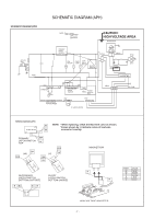
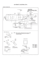
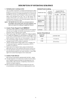
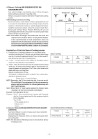
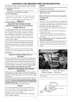
DESCRIPTION OF OPERATING SEQUENCE 1. Variable power cooking control The coil of power relay B (RY1) is energized intermittently by the digital programmer circuit, when the oven is set at any power selection except for High power position. The digital programmer circuit controls the ON-OFF time of power relay B contacts in order to vary the output power of the microwave oven from "Low" to "High" power. One complete ON and OFF cycle of power relay B is 22 seconds. The relation between indications on the control panel and the output of the microwave oven is as shown in table. NOTE: The ON/OFF time ratio does not correspond with the percentage of microwave power since approximately 2 seconds are required for heating of magnetron filament. 2. Inverter Power Supply Circuit NEW H,V This Inverter Power Supply Circuit supplies 4,000V DC to the magnetron tube from the line voltage,120v 60Hz AC input. functions as the H.V. transformer, the H.V.capacitor and H.V.Diode. 1. The AC input voLtage 120V 60HZ is rectified to DC voltage immediately. 2. DC voltage will be supplied to the switching devices called IGBT. These devices will be switched ON-OFF by the 20 to 40 kHz PWM. (pulse width modulation) signal from the microcomputer in the DPC. 3. This drives the High voltage transformer to increase up to 2,000V AC and approximately 3V AC by means of transformer. 4. Then the half-wave doubler voltage rectifier circuit, consisting of the HV diodes and Capacitors, generates the necessary 4,000V DC needed for the magnetron. 5. Output power of the magnetron tube is always monitored by the signal output from the current transformer built into the inverter ciruit. 6. Then this signal will be fed back to the microcomputer in the DPC to determine operating conditions and output necessary to control PWM signal to the inverter Power Supply to control output power. Variable Power Cooking POWER SETTING OUTPUT POWER(%) APPROX. HIGH P10 P9 P8 MEDIUM-HIGH P7 MEDIUM P6 P5 P4 MEDIUM-LOW P3 P2 P1 DEFROST P3 100% 90% 80% 70% 60% 50% 40% 30% 20% 10% 30% ON-OFF TIME OF POWER RELAY B (RY1) ON (SEC) 22 22 22 22 22 22 22 22 15 8 22 OFF (SEC) 0 0 0 0 0 0 0 0 7 14 0 Inverter Turbo Defrost SELECTED WEIGHT 1.0LB 6.0LB COOKING TIME 4 min.28 sec. 25 min.00 sec. 3. Inverter Turbo Defrost When this Auto Control feature is selected and the Start Pad is tapped: (A) The digital programer circuit determines the power level and cooking time to complete cooking and indicates the operating state in the display window. Table shows the corresponding cooking times for respective serving by categories. (B) When cooking time the display window has elapsed, the oven tums off automatically by a control signal from the digital programmer circuit. - 9 -
-
 1
1 -
2
-
3
-
4
-
 5
5 -
 6
6 -
 7
7 -
 8
8 -
 9
9 -
 10
10 -
 11
11 -
 12
12 -
 13
13 -
 14
14 -
 15
15 -
16
-
17
-
18
-
19
-
20
-
21
-
22
-
23
-
24
-
25
-
26
-
27
-
28
-
29
-
30
-
31
-
32
-
33
-
34
-
35
-
36
 |
 |