Panasonic 1100W Service Manual - Page 17
Component Test Procedure
 |
UPC - 074000617384
View all Panasonic 1100W manuals
Add to My Manuals
Save this manual to your list of manuals |
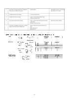
Page 17 highlights
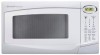
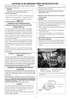
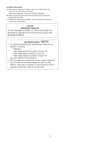
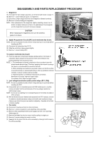
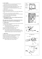
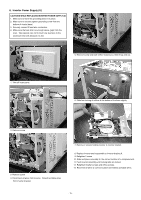
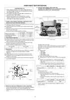
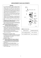
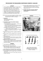
COMPONENT TEST PROCEDURE CAUTION NEW. H.V. 1. High voltage is present at the high voltage terminal of the High Voltage Inverter (U) including aluminum heat sink during any cook cycle. 2. It is neither necessary nor advisable to attempt measurement of the high voltage. 3. Before touching any oven components, or wiring, always unplug the oven from its power source and discharge the high voltage capacitors. 5. Inverter Power Supply (U)for USA only DO NOT try to REPAIR this H.V. Inverter power supply (U).Replace as whole H.V. Inverter(U) Unit. DO NOT TOUCH (HOT/HIGT VOLTAGE) HEAT SINK 1. Primary Latch Switch, Secondary (Secondary Latch HIGH BOLTAGE TRANSFORMER Switch and Power Relay B) Interlocks. (A) Unplug the lead connectors to Power Relay B and verify continuity CHOKE COIL of the power relay B 1-2 terminals. FILM CAPACITORS (B) Unplug lead connectors to Primary Latch Switch and Secondary Latch Switch. CURRENT TRANSFORMER VARISTOR (C) Test the continuity of switches at door opened and closed positions with ohm meter (low scale). Normal continuity readings should be as follows. RESISTOR SAND BAR PRIMARY WINDINGS SECONDARY Door Closed Door Opened PCB WINDINGS Primary Latch Switch Secondary Latch Switch 0 Ω (close) 0 Ω (close) Ω (open) Ω (open) HIGH VOLTAGE DIODES Power Relay B Ω (open) Ω (open) 2. Short Switch & Monitor (A) Unplug lead wires from Inverter Power Supply (U) primary terminals. (B) Connect test probes of ohm meter to the disconnected leads which DO NOT TOUCH 4 were connected to Inverter Power Supply (U). (C) Test the continuity of short switch with door opened and closed positions using lowest scale of the ohm meter. Normal continuity readings should be as follows. DANGER HIGH VOLTAGE Door Opened 0 Ω 3. Magnetron Door Closed Ω Test if failure codes of H97 or H98 appears by doing the following procedure. It is recommended to use an AC line input current Ampere meter for testing. Test 1 Continuity checks can only indicate an open filament or a shorted A. Program DPC. magnetron. To diagnose for an open filament or shorted magnetron. (A) Isolate magnetron from the circuit by disconnecting the leads. (B) A continuity check across magnetron filament terminals should indicate one ohm or less. (C) A continuity check between each filament terminal and magnetron case should read open. 1. Tap Clock 2. Tap TIMER 3. Tap START 4. Tap POWER LEVEL B. Place 1 liter of water load into oven cavity. C. Unplug 2 pin H.V. lead wire connector CN703 from magnetron tube. D. Program oven at High power for 1 minute and press start. 1. After approximately 15 seconds, oven displays H98 and stops oven. ANTENNA 2. During oven operation, input current is approximately 1.0 to 1.7A. If both 1 and 2 are OK, please proceed to test 2. ANTENNA GASKET INPUT AMPERE FAILURE CODE COOLING FIN MAGNETRON CASE HIGHEST OHM SCALE 0Ω-1Ω RX1 SCALE FILAMENT TERMINALS Unplug CN703 1.0 to 1.7A H98 . Test 2. Continued from Test 1 A. Unplug 3 pin connector, CN701 B. Set oven at High power for 1 minute and start. 1. After approximately 27 seconds, oven displays H97 and stops oven. 2. During oven operation, input current is approximately 0.4 to 0.8A 04-031M Unplug CN701 INPUT AMPERE 0.4 to 0.8A FAILURE CODE H97 4. Membrane key board (Membrane switch assembly) Check continuity between switch terminals, by tapping an appropriate pad on the key board. The contacts assignment of the respective pads on the key board is as shown in digital programmer circuit. If both 1 and 2 are OK, the Inverter Power Supply (U) can be determined OK. - 16 -
-
 1
1 -
2
-
3
-
4
-
5
-
6
-
7
-
8
-
9
-
10
-
11
-
 12
12 -
 13
13 -
 14
14 -
 15
15 -
 16
16 -
 17
17 -
 18
18 -
 19
19 -
 20
20 -
 21
21 -
 22
22 -
23
-
24
-
25
-
26
-
27
-
28
-
29
-
30
-
31
-
32
-
33
-
34
-
35
-
36
 |
 |