Panasonic CF-19CDBAXVM Service Manual - Page 23
Removing the DIMM Lid Ass'y, Removing the Rear Cabinet
 |
UPC - 092281864785
View all Panasonic CF-19CDBAXVM manuals
Add to My Manuals
Save this manual to your list of manuals |
Page 23 highlights
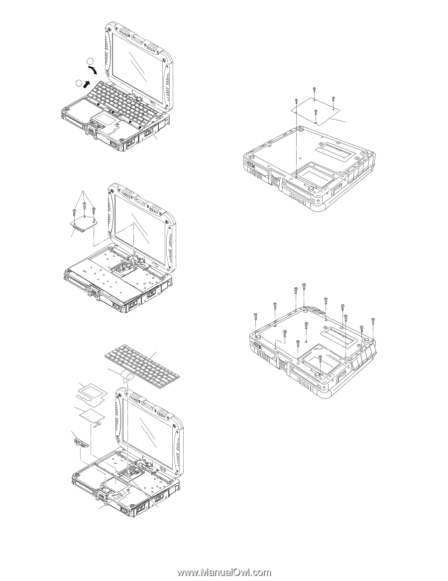
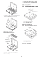
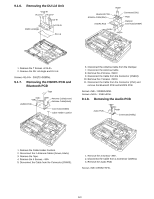
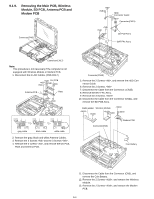
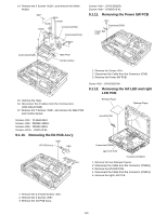
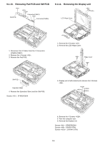
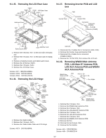
1 2 10. Disconnect the Cable from Connector (CN800). 11. Remove the Touch Pad and Click Button Plate. Screws : DFHE5025XA Screws : DRSB2+5FKL 9.1.4. Removing the DIMM Lid Ass'y DIMM Lid Ass'y Keyboard 4. Lift the far side of the Keyboard and slide it to backward, and then turn the Keyboard over frontward. KBD Connector Cover 5. Remove the 3 Screws . 6. Remove the KBD Connector Cover. Keyboard Keyboard FPC TP Tape Touch Pad Click Button Plate 1. Remove the 4 Screws . 2. Remove the DIMM Lid Ass'y. Screws : DRHM5025YAT 9.1.5. Removing the Rear Cabinet 1. Remove the 13 Screws . 2. Open the LID Rubbers. 3. Remove the Rear Cabinet. Screws : DRHM0061ZA Connector (CN800) Connector (CN18) 7. Disconnect the Cable from Connector (CN18). 8. Remove the Keyboard. 9. Remove the TP Tape. 9-2
-
 1
1 -
2
-
3
-
4
-
5
-
6
-
7
-
8
-
9
-
10
-
11
-
12
-
13
-
14
-
15
-
16
-
17
-
 18
18 -
 19
19 -
 20
20 -
 21
21 -
 22
22 -
 23
23 -
 24
24 -
 25
25 -
 26
26 -
 27
27 -
 28
28 -
29
-
30
-
31
-
32
-
33
-
34
-
35
-
36
-
37
-
38
-
39
-
40
-
41
-
42
-
43
-
44
-
45
-
46
-
47
-
48
-
49
-
50
-
51
-
52
-
53
-
54
-
55
-
56
-
57
-
58
-
59
-
60
-
61
-
62
-
63
-
64
-
65
-
66
-
67
-
68
-
69
-
70
-
71
-
72
-
73
-
74
-
75
-
76
-
77
-
78
-
79
-
80
-
81
-
82
-
83
-
84
 |
 |