Panasonic CF-19CDBAXVM Service Manual - Page 30
Reassembly Instructions - details
 |
UPC - 092281864785
View all Panasonic CF-19CDBAXVM manuals
Add to My Manuals
Save this manual to your list of manuals |
Page 30 highlights
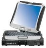
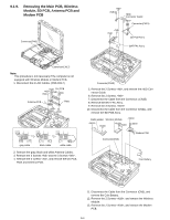
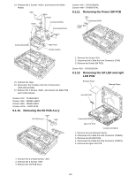
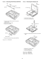
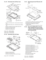
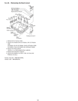
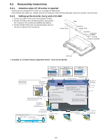
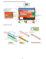
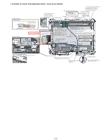
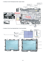
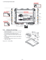
9.2. Reassembly Instructions 9.2.1. Attention when CF-19 series is repaired • Please execute writing BIOS ID when you exchange the Main Board. • Parts (Sheet and rubber) etc. related various the Conductive Cloth and Heat Spreader cannot be recycled. Use new parts. 9.2.2. Setting up the Inverter Ass'y and LCD UNIT 1. Set the LCD UNIT to the LCD Front Cabinet/TS Panel. 2. Set the TS PCB on the LCD Back Damper, and connect the 2 Cables to the Connectors (CN900 and CN901). 3. Set the Inverter PCB to the LCD Back Damper, and con- nect the 2 Cables to the Connectors. Inverter Case Tape Connector Inverter PCB Connector Connector (CN901) TS PCB Connector (CN900) LCD Unit n Assembly of LCD Back Damper (Applicable Model : Touch Screen Model) Detail of "B" 0 1mm Detail of "C" 0 1mm Detail of "D" 0 1mm 0 0.5mm Pass the Cable 0 0.5mm under the protrusion. Pass the Cable through the space. 1 1.5mm Pass the Cable under the protrusion. LCD Side Cushion S B C Note: Apply the load to attach. 20 to 30N (2.0 to 3.0 Kgf) Order of fixing After setting LCD Back Damper, fix them together. Screw Detail of "A" A 0 3mm LCD Back Damper Holder Sheet LCD Back Cushion Side LCD Back Cushion L LCD Back Cushion S D After setting LCD Back Damper, fix them together. Remove the Release Paper on Holder Sheet the back side and attach it. Lengthwise: Match to the LCD Frame. Crosswise: Match to the middle line. LCD Back Cushion Side Screw 0 0.5mm 0 0.5mm 0 0.5mm LCD Side Cushion A Attach to the side surface if the Frame. (Match to the end of the Frame within 0 to 0.5 mm at the far side.) LCD PWB SPACER ASSY Insert this between LCD PCB & LCD Frame. Cover the hook of the Frame. (0 to 0.5 mm) Match both Holder Sheet and LCD Back Cushion Side to the right edge of the Frame. (0 to 0.5 mm) Cover the hook of the Frame. (0 to 0.5 mm) Match both Holder Sheet and LCD Back Cushion Side to the right edge of the Frame. (0 to 0.5 mm) LCD PWB SPACER ASSY Spacer Sheet LCD PCB Spacer Screw Screw the Board and the Spacer together. Spacer Sheet LCD Side Cushion C 0 0.5mm Asymmetric Shape 0.5mm LCD Side Cushion D LCD Side Cushion C 0.5mm Screw Screw the Board and the Spacer together. 0.5mm 0.5mm 0.5mm 9-9
-
 1
1 -
2
-
3
-
4
-
5
-
6
-
7
-
8
-
9
-
10
-
11
-
12
-
13
-
14
-
15
-
16
-
17
-
18
-
19
-
20
-
21
-
22
-
23
-
24
-
 25
25 -
 26
26 -
 27
27 -
 28
28 -
 29
29 -
 30
30 -
 31
31 -
 32
32 -
 33
33 -
 34
34 -
 35
35 -
36
-
37
-
38
-
39
-
40
-
41
-
42
-
43
-
44
-
45
-
46
-
47
-
48
-
49
-
50
-
51
-
52
-
53
-
54
-
55
-
56
-
57
-
58
-
59
-
60
-
61
-
62
-
63
-
64
-
65
-
66
-
67
-
68
-
69
-
70
-
71
-
72
-
73
-
74
-
75
-
76
-
77
-
78
-
79
-
80
-
81
-
82
-
83
-
84
 |
 |