Panasonic CF-19CDBAXVM Service Manual - Page 28
LAN AUX Antenna PCB and WWAN
 |
UPC - 092281864785
View all Panasonic CF-19CDBAXVM manuals
Add to My Manuals
Save this manual to your list of manuals |
Page 28 highlights
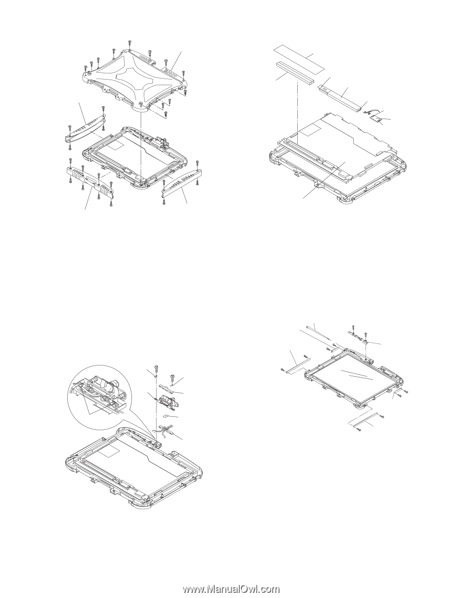
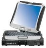
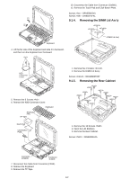
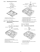
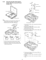
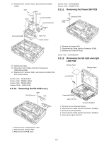
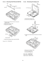
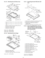
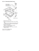
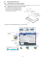
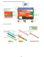
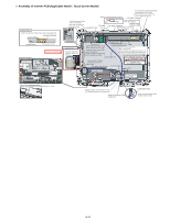
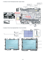
9.1.15. Removing the LCD Rear Case LCD Rear Case Antenna Cover Tablet Latch Cover Antenna Cover 1. Remove the 8 Screws on the front side of Display unit. 2. Remove the 8 Screws on the back side of Display unit. 3. Remove 2 Antenna Covers and Tablet Latch Cover. 4. Remove the 10 Screws . 5. Remove the 2 Screws . 6. Remove the LCD Rear Case. Screws : DRQT26+E5FKL Screws : DXYN2+J6FNL Screws : DXYN3+J10FNL 9.1.16. Removing the LCD Hinge Cable Holder Plate Cable Holder Plate Cable Holder LCD Plate Hinge Cable Holder LCD Cable Holder Sheet Cable Holder 1. Remove the Cable Holder. 2. Remove the 2 Screws . 3. Remove the Cable Holder Plate and LCD Hinge. Screws : DXYN3+J8FNL 9.1.17. Removing Inverter PCB and LCD Unit Tape Inverter Case Connector Inverter PCB Connector Connector (CN901) TS PCB Connector (CN900) LCD Unit 1. Disconnect the 2 Cables from 2 Connectors (CN1,CN2). 2. Remove the Inverter Case and Inverter PCB. 3. Disconnect the 2 Cable from 2 connector (CN900,CN901). 4. Remove the TS PS2 PCB, then remove the LCD unit. 9.1.18. Removing WWAN Main Antenna PCB, LAN-Main BT Antenna PCB, LAN AUX Antenna PCB and WWAN AUX Antenna PCB WWAN Aux Pen Antenna PCB LAN-Main BT Antenna PCB Pen Holder LAN Aux Antenna PCB WWAN Main Antenna PCB 1. Remove the 2 Screws . 2. Remove the WWAN Main Antenna PCB. 3. Remove the 2 Screws . 4. Remove the LAN-Main BT Antenna PCB. 5. Remove the 2 Screws . 6. Remove the LAN AUX Antenna PCB. 7. Remove the 2 Screws . 8. Remove the WWAN AUX Antenna PCB. 9. Remove the Pen 10. Remove the two Screws . 11. Remove the Pen Holder. Screws : DFHE5025XA Screws : DRHM5025YA 9-7
-
 1
1 -
2
-
3
-
4
-
5
-
6
-
7
-
8
-
9
-
10
-
11
-
12
-
13
-
14
-
15
-
16
-
17
-
18
-
19
-
20
-
21
-
22
-
 23
23 -
 24
24 -
 25
25 -
 26
26 -
 27
27 -
 28
28 -
 29
29 -
 30
30 -
 31
31 -
 32
32 -
 33
33 -
34
-
35
-
36
-
37
-
38
-
39
-
40
-
41
-
42
-
43
-
44
-
45
-
46
-
47
-
48
-
49
-
50
-
51
-
52
-
53
-
54
-
55
-
56
-
57
-
58
-
59
-
60
-
61
-
62
-
63
-
64
-
65
-
66
-
67
-
68
-
69
-
70
-
71
-
72
-
73
-
74
-
75
-
76
-
77
-
78
-
79
-
80
-
81
-
82
-
83
-
84
 |
 |