Panasonic CF-29CRKGZKM Service Manual - Page 28
Reassembly Instructions, Attention when CF, series is repaired, Setting the Antenna PCB L and R
 |
UPC - 092281833422
View all Panasonic CF-29CRKGZKM manuals
Add to My Manuals
Save this manual to your list of manuals |
Page 28 highlights
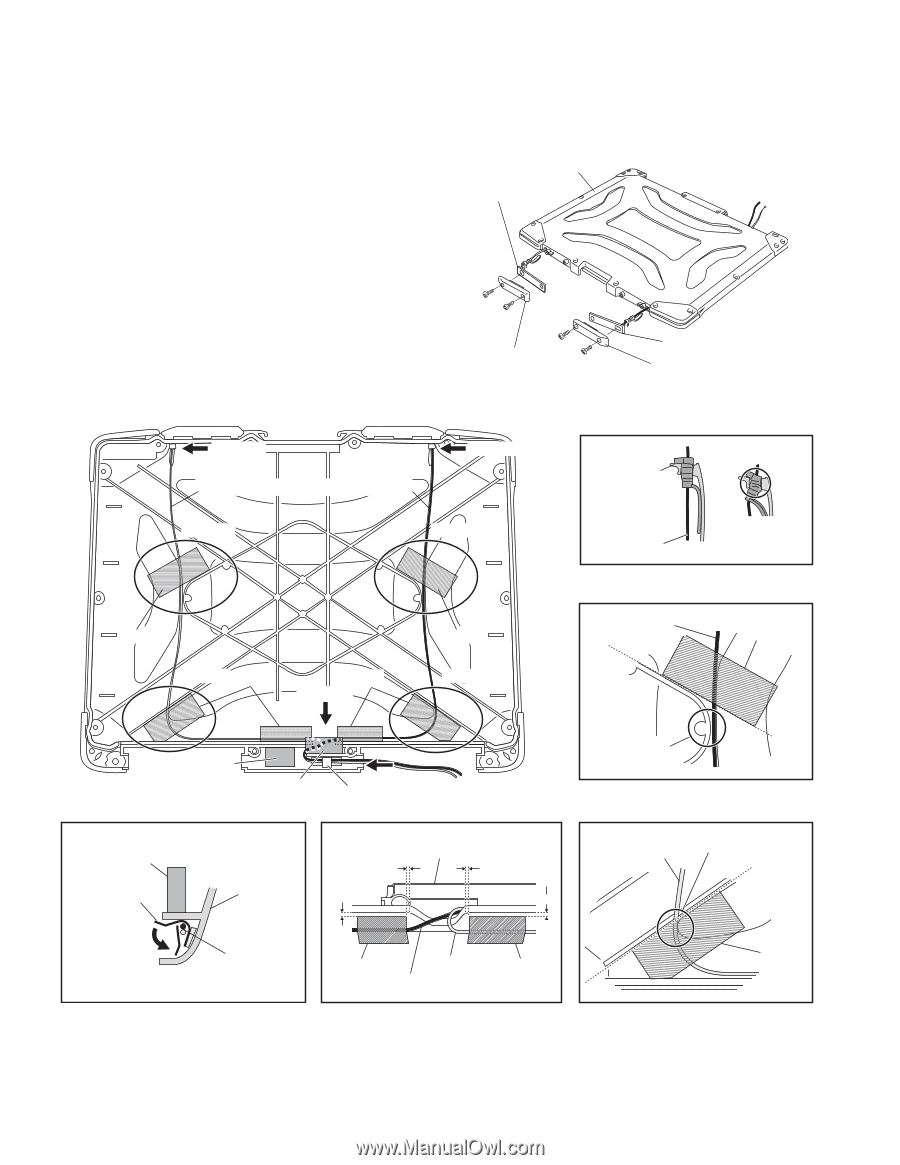
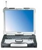
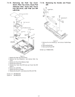
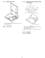
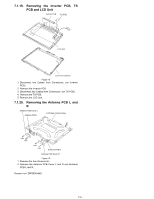
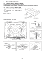
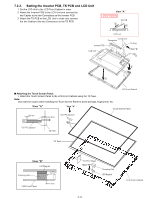
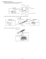
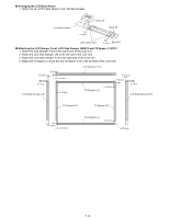
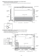
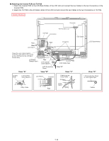
7.2. Reassembly Instructions 7.2.1. Attention when CF-29 series is repaired • Please execute writing BIOS ID when you exchange the Main Board. • You cannot reuse the Conductive Clothes and the heat dissipating parts such as Sheet and Rubber. Use new parts. 7.2.2. Setting the Antenna PCB L and R 1. Set the Antenna PCB L and R to the LCD Rear Cabinet Ass'y. 2. Fix the Antenna PCB Cover L and R using the four Screws. Screws : DRSB26+8KL LCD Rear Cabinet Ass'y Antenna PCB L n Arranging the Antenna L and R Cables View "A" Antenna Cable L Antenna Cable R Antenna PCB Cover L Antenna PCB R Antenna PCB Cover R View "A" View "A" LCD Rear Cabinet View "B" View "B" Antenna Cable Do not press too much the Waterproof Cap. Tape Tape View "B" Antenna Cable R Tape View "C" Tape Tape View "D" View "C" Cushion Waterproof Cushion View "E" Cable Clamper View "E" View "D" Waterproof Cushion Cable Clamper LCD Rear Cabinet LCD Rear Cabinet 1~5mm 1~5mm 1~4mm 1~4mm Pass the Antenna Cable through this space. align View "C" Pass the Antenna Cable through this space. Antenna Cable L align Bend Antenna Cable L and R Tape Antenna Cable L Tape Antenna Cable R Tape 7-10
-
 1
1 -
2
-
3
-
4
-
5
-
6
-
7
-
8
-
9
-
10
-
11
-
12
-
13
-
14
-
15
-
16
-
17
-
18
-
19
-
20
-
21
-
22
-
 23
23 -
 24
24 -
 25
25 -
 26
26 -
 27
27 -
 28
28 -
 29
29 -
 30
30 -
 31
31 -
 32
32 -
 33
33 -
34
-
35
-
36
-
37
-
38
-
39
-
40
-
41
-
42
-
43
-
44
-
45
-
46
-
47
-
48
-
49
-
50
-
51
-
52
-
53
-
54
-
55
-
56
-
57
-
58
-
59
-
60
-
61
-
62
-
63
-
64
-
65
-
66
-
67
-
68
-
69
-
70
-
71
-
72
-
73
-
74
-
75
-
76
-
77
-
78
-
79
-
80
-
81
-
82
-
83
-
84
-
85
-
86
-
87
-
88
-
89
-
90
-
91
-
92
-
93
-
94
-
95
-
96
-
97
-
98
-
99
-
100
-
101
-
102
-
103
-
104
 |
 |