Panasonic CYTUN153U CYTUN153U User Guide - Page 11
Installation, Preparation
 |
View all Panasonic CYTUN153U manuals
Add to My Manuals
Save this manual to your list of manuals |
Page 11 highlights
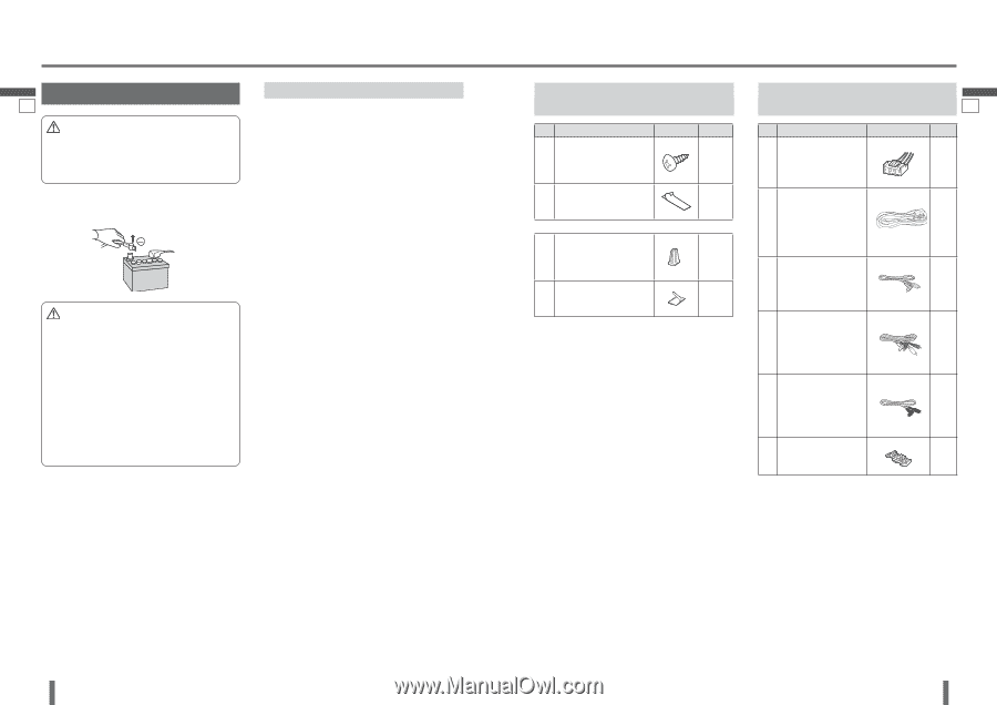
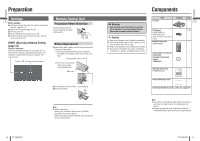
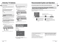
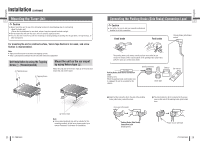
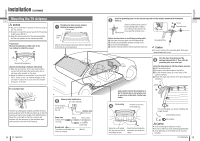
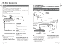
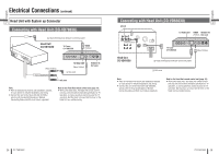
English English Installation Preparation 19 Caution Please follow the laws and regulations of your province or country for installation of the unit. We strongly recommended you to wear gloves for installation work to protect yourself from injuries. Disconnect the cable from the negative () battery terminal (see caution below). Caution If your car is equipped with air bag and/or antitheft systems specific procedures may be required for connection and disconnection of the battery to install this product. Before attempting installation of this electronic component contact your car dealer or manufacturer to determine the required procedure and strictly follow their instructions. FAILURE TO FOLLOW THE PROCEDURE MAY RESULT IN THE UNINTENDED DEPLOYMENT OF AIR BAGS OR ACTIVATION OF THE ANTI-THEFT SYSTEM RESULTING IN DAMAGE TO THE VEHICLE AND PERSONAL INJURY. Installation Precautions This unit should be installed by a professional installer. In case of difficulty, please consult your nearest authorized Panasonic Servicenter. This system is to be used only in a 12 V DC battery system (car) with negative ground. Follow the electrical connections carefully (page 26). Failure to do so may result in damage to the unit. Connect the power lead after all other connections are made. Be sure to connect the battery lead (yellow) to the positive terminal () of the battery or fuse block (BAT) terminal. Insulate all exposed wires to prevent short circuiting. Secure all loose wires after installing the unit. Please carefully read the operating instructions of the respective equipment before connecting it to this unit. Installation Hardware (For Installation) No. Item Tapping Screw (516 mm) (XTT516AFZ) Diagram Qty. 4 Velcro Tape 2 (YFX994C135ZA) Antenna Clamp 4 Cord Clamp (for antenna) 4 (YEP9FZ3041) Installation Hardware (For Wiring) No. Item Power Connector (YEAJ012884) Diagram 20 Qty. 1 Head Unit/Expansion 1 Module Connecting Cable (3 m) (YEAJ071812) (for Expansion Module) RCA Cord (3 m) 1 (YEAJ071819) (for video connector) RCA Cord (3 m) 1 (YEAJ071820) (for audio connector) RCA Cord (3 m) 1 (YEAJ071821) (for remote control connector) Clip Connector 1 (YEAT034C012) Note: The number in parenthesis underneath each accessory part name is the part number for maintenance and service. Accessories and their parts numbers are subject to modification without prior notice due to improvements. Use the supplied screws for installation exclusively. In case of losing any of them, please order the specific screw. 20 CY-TUN153U CY-TUN153U 21
-
 1
1 -
2
-
3
-
4
-
5
-
 6
6 -
 7
7 -
 8
8 -
 9
9 -
 10
10 -
 11
11 -
 12
12 -
 13
13 -
 14
14 -
 15
15 -
 16
16 -
17
-
18
-
19
-
20
-
21
-
22
-
23
-
24
-
25
-
26
-
27
-
28
-
29
-
30
-
31
-
32
-
33
-
34
-
35
-
36
-
37
-
38
-
39
-
40
-
41
-
42
-
43
-
44
-
45
-
46
-
47
-
48
-
49
-
50
-
51
-
52
 |
 |