Panasonic FV08VKSL4 FV08VKL4 User Guide - Page 8
Acaution
 |
View all Panasonic FV08VKSL4 manuals
Add to My Manuals
Save this manual to your list of manuals |
Page 8 highlights
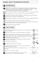
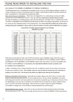
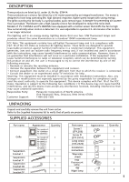
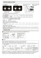
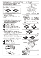
INSTALLATION I (JOIST MOUNTING - I) Joist situation: Spacing A is 16 inches (406 mm) to 24 inches Joists (609 mm) on center joists 1. If the spacing A is 16 inches (406 mm) to 24 inches (609 mm) on center joists, please follow the installation step as below. IMPORTANT: Remove the tape from damper and adaptor before installation. As shown below: Adaptor__ Damper Tape 2. Insert the suspension bracket I and II into the fan body. (Select the suspension bracket connection holes as shown below) (Fig.1) Suspension bracket connect method: Suspension bracket I and II connect with screw I as shown below: Unit: inches (mm) Suspension bracket II T4h 13 1/4 - 15 1/2 (336-394) 16 1/2 -18 3/4 (419-480) ' 4 21 1/4 - 23 1/2 (540-597) v% Suspension WI- Screw I bracket I (ST4.2X6) 3. Install the suspension bracket and the flange of frame to joists by using long screws (ST4.2X20) and secure it to the fan body by using screw II (ST4.2X14). (Fig.2) 4.Install a circular duct and secure it with clamps, or wire ties and seal it with mastic or approved duct tape. 4 inches circular duct or 6 inches circular duct is needed to connect to relevant part of common adaptor.(Fig.3) 5. Remove junction box cover and secure conduit or stress relief to junction box knock-out hole. (Fig.3) 6. Refer to wiring diagram. (Wiring detail please refer to the wiring diagram on page 6) Follow all the local electrical safety codes as well as the National Electrical Code (NEC). Using UL approved wire nuts, connect house power wires to ventilating fan wires. (Fig.4-1, Fig.4-2) ACAUTION 0 Mount junction box cover carefully so that lead wires are not pinched. Fan body cp Suspension bracket II Joists Suspension bracket I &II Suspension bracket I Fig.1 Sensor unit (FV-13VKML4 & FV-08VKML4 only) 4 Long screws (ST4.2X20) O Joist 0\ 0 2 Long screws (ST4.2X20) screw II (ST4.2X14) Fig.2 Knock-out hole Circular duct Conduit Duct tape Junction box cover Conduit Junction box Live to black (Night lamp) Sensor unit (FV-13VKML4 & FV-08VKML4 only) Fig.3 Ferrite Core (For reducing the electromagnetic noise) Earth ground to green Wire nut Netural to white Netural to white Live to black e(Fluorescent lamp) Live to black (Ventilating fan) FV-13VKML4 FV-13VKL4 FV-11VKL4 FV-08VKML4 FV-08VKL4 Fig.4-1 8
-
 1
1 -
2
-
 3
3 -
 4
4 -
 5
5 -
 6
6 -
 7
7 -
 8
8 -
 9
9 -
 10
10 -
 11
11 -
 12
12
 |
 |
