Panasonic FV08VKSL4 FV08VKL4 User Guide - Page 9
Fv-13vksl4
 |
View all Panasonic FV08VKSL4 manuals
Add to My Manuals
Save this manual to your list of manuals |
Page 9 highlights
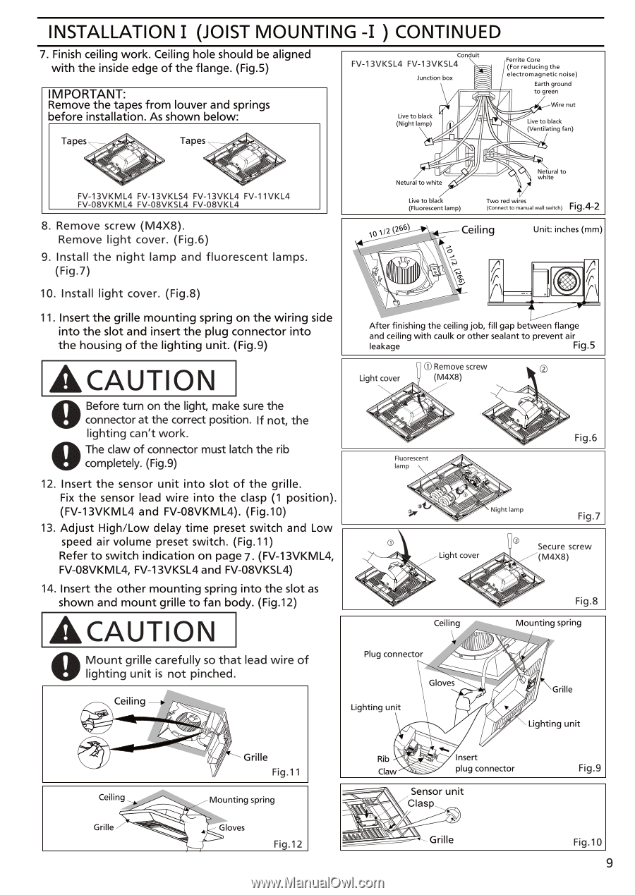
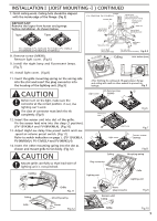
INSTALLATION I (JOIST MOUNTING -I ) CONTINUED 7. Finish ceiling work. Ceiling hole should be aligned with the inside edge of the flange. (Fig.5) MPORTANT: Remove the tapes from louver and springs before installation. As shown below: Tapes Tapes Conduit FV-13VKSL4 FV-13VKSL4 Junction box Live to black (Night lamp) Ferrite Core (For reducing the electromagnetic noise) Earth ground to green Wire nut Live to black (Ventilating fan) FV-13VKML4 FV-13VKLS4 FV-13VKL4 FV-11VKL4 FV-08VKML4 FV-08VKSL4 FV-08VKL4 8. Remove screw (M4X8). Remove light cover. (Fig.6) 9. Install the night lamp and fluorescent lamps. (Fig.7) 10. Install light cover. (Fig.8) Netural to white Live to black (Fluorescent lamp) Netural to V Two red wires (Connect to manual wall switch) Fig.42 .1/2 k266) Ceiling Unit: inches (mm) 0 vs 1.3 7 11. Insert the grille mounting spring on the wiring side into the slot and insert the plug connector into the housing of the lighting unit. (Fig.9) After finishing the ceiling job, fill gap between flange and ceiling with caulk or other sealant to prevent air leakage Fig.5 ACAUTION Light cover ® Remove screw (M4X8) O Before turn on the light, make sure the connector at the correct position. If not, the lighting can't work. O The claw of connector must latch the rib completely. (Fig.9) 12. Insert the sensor unit into slot of the grille. Fix the sensor lead wire into the clasp (1 position). (FV-13VKML4 and FV-08VKML4). (Fig.10) 13. Adjust High/Low delay time preset switch and Low speed air volume preset switch. (Fig.11) Refer to switch indication on page 7. (FV-13VKML4, FV-08VKML4, FV-13VKSL4 and FV-08VKSL4) 14. Insert the other mounting spring into the slot as shown and mount grille to fan body. (Fig.12) ACAUTION O Mount grille carefully so that lead wire of lighting unit is not pinched. Ceiling Fluorescent lamp Light cover Ceiling 40 Plug connector Lighting unit Gloves 4 .P#40, -(> Fig.6 Night lamp Fig.7 I Secure screw (M4X8) Fig.8 Mounting spring v40 0 e (4 I Grille 107 Lighting unit Ceiling Grille Fig.11 Mounting spring ha 444* Rib V Claw 44*.74 7.s Insert plug connector Sensor unit Clasp Fig.9 Grille Gloves Fig.12 Grille Fig.10 9
-
 1
1 -
2
-
3
-
 4
4 -
 5
5 -
 6
6 -
 7
7 -
 8
8 -
 9
9 -
 10
10 -
 11
11 -
 12
12
 |
 |