Panasonic PT47WXD64J PT47WXD64 User Guide - Page 10
Optional Equipment Connections, Vcr Connection, Cablecard Connection
 |
View all Panasonic PT47WXD64J manuals
Add to My Manuals
Save this manual to your list of manuals |
Page 10 highlights
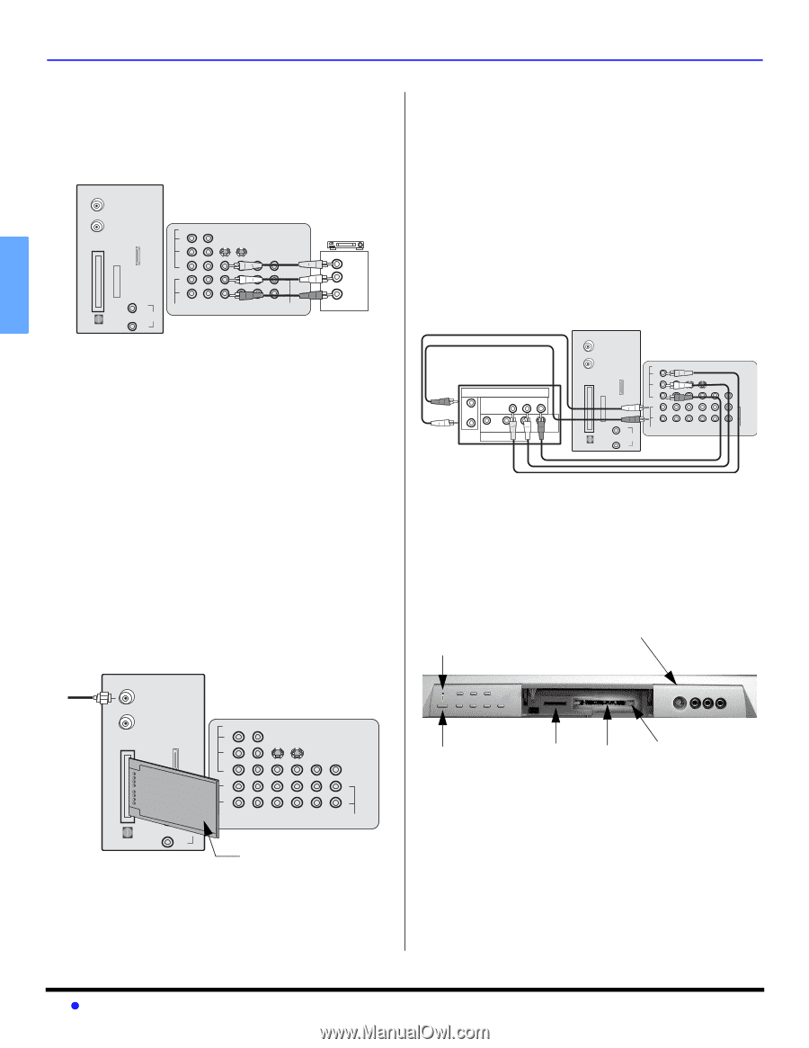
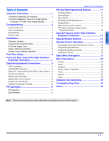
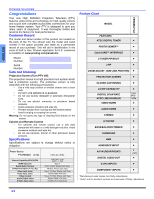
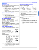
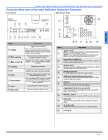
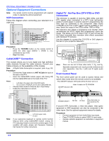
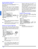
ENGLISH L-AUDIO-R OPTIONAL EQUIPMENT CONNECTIONS Optional Equipment Connections Note: The remote control must be programmed with supplied codes to operate the optional equipment. VCR Connection Follow this diagram when connecting your television to a VCR only. ANT A Cable In ANT B TERMINALS ON BACK OF PROJECTION TELEVISION CableCARD TM INTERFACE HDMI SERVICE ONLY AV IN DIGITAL AUDIO OUT L AUDIO IN R VIDEO Y PB S-VIDEO PR VIDEO LL L RR 1 2 AUDIO COMPONENT VIDEO INPUT INPUT 1 INPUT 2 R INPUT PROG TO AUDIO 3 OUT AMP CABLES NOT SUPPLIED VCR PLAY R E FF W STOP VIDEO OUT L AUDIO OUT R Procedure • Press the TV/VIDEO button on the remote control to select the video input (VIDEO 1, VIDEO 2, etc.) connected to your VCR. • Begin the video. CableCARD™ Connection This module allows you to tune digital and high definition cable channels through the cable antenna. Consult your Cable company on the availability of this module. Note: A Digital Cable Subscription is required. (refer to pg. 29) Procedure • Connect the Cable antenna to ANT A/Cable In input on the back of the PTV. • Insert the CableCARD module (upper side facing left) into the CableCARD slot on the back of the PTV. Notes: • • • Left side is the upper side of the DCM cards. • Do not insert a PCMCIA card into the CableCARD slot. Choose Cable mode for Antenna (A) in Input Setup. Follow the instructions on screen. ANT A Cable In Incoming cable signal ANT B CableCARDTM INTERFACE HDMI SERVICE ONLY A/V IN INSERT THIS END CableCARDTM DIGITAL AUDIO OUT L AUDIO IN R TERMINALS ON BACK OF PROJECTION TELEVISION VIDEO Y PB S-VIDEO PR VIDEO L L R 1 2 AUDIO COMPONENT VIDEO INPUT INPUT 1 R INPUT INPUT PROG TO AUDIO 2 3 OUT AMP Left side (upper side) of card Note: If you experience keyboard or remote control function hang-up when using CableCARD module, unplug the PTV and plug it back on and try the controls again. If this condition still exists, please call Panasonic Customer Call Center for further instructions. Digital TV - Set-Top Box (DTV-STB) or DVD Connection This television is capable of receiving 1080i, 480p, and 480i DTV signals when connected to a DTV tuner set-top-box (STB) or a DVD player. In order to view DTV programming, the STB must be connected to the component video inputs (Y,PB,PR) of the PTV. A DTV signal must be available in your area. Select the output of the STB to either 1080i or 480p. This television also utilizes a progressive scan doubler, which de-interlaces the NTSC signal and progressively scans the image. This allows you to sit close to the TV and not see the thin black horizontal lines (venetian blind effect) associated with interlaced TV pictures. Use this diagram to connect the DTV-STB or DVD player to the back of your projection television. TERMINALS ON BACK OF PROJECTION TELEVISION ANT A Cable In TERMINALS ON BACK OF DTV-STB OR DVD PLAYER DIGITAL TV OUTPUT Y MAIN VIDEO PB PR R-AUDIO-L - VIDEO S-VIDEO NTSC OUTPUT ANT B CableCARD TM INTERFACE HDMI SERVICE ONLY AV IN DIGITAL AUDIO OUT L AUDIO IN R VIDEO Y PB S-VIDEO PR VIDEO LL L R R 1 2 AUDIO COMPONENT VIDEO INPUT INPUT 1 INPUT 2 R INPUT PROG TO AUDIO 3 OUT AMP CABLES NOT SUPPLIED Note: There are two set of three video iacks, Y, PB, and PR. Separate component color inputs provide luminance and color separation. Use the L (left) and R (right) audio inputs. Front Control Panel The front control panel can be used to access menus and switch video mode when the remote control is not available. The ON/OFF indicator LED (red) will be lit when set is on. Video 4 location for PT-47WXD64 ON/OFF Indicator LED CHANNEL TV/VIDEO POWER VOLUME OK MENU S-VIDEO VIDEO 4 L - AUDIO - R POWER ON/OFF SD Slot PC Slot Press this button to eject card from PC slot. A second VCR, Camcorder, a video disc player, video game equipment or DSS equipment can also be connected to the video inputs. See the optional equipment manual for details. Procedure • Connect equipment to front Audio/Video input jacks. • Press TV/VIDEO button to select VIDEO 4 input mode. • Operate optional equipment as instructed in equipment manual. 8 z
-
 1
1 -
2
-
3
-
4
-
 5
5 -
 6
6 -
 7
7 -
 8
8 -
 9
9 -
 10
10 -
 11
11 -
 12
12 -
 13
13 -
 14
14 -
 15
15 -
16
-
17
-
18
-
19
-
20
-
21
-
22
-
23
-
24
-
25
-
26
-
27
-
28
-
29
-
30
-
31
-
32
-
33
-
34
-
35
-
36
-
37
-
38
-
39
-
40
-
41
-
42
-
43
-
44
-
45
-
46
-
47
-
48
-
49
-
50
-
51
-
52
-
53
-
54
-
55
-
56
-
57
-
58
-
59
-
60
-
61
-
62
-
63
-
64
-
65
-
66
-
67
-
68
-
69
-
70
-
71
-
72
-
73
-
74
-
75
-
76
-
77
-
78
-
79
-
80
-
81
-
82
-
83
-
84
-
85
-
86
-
87
-
88
 |
 |