Panasonic SAHE75 SAHE75 User Guide - Page 6
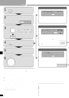
Step 2 - Equipment Connections
 |
View all Panasonic SAHE75 manuals
Add to My Manuals
Save this manual to your list of manuals |
Page 6 highlights
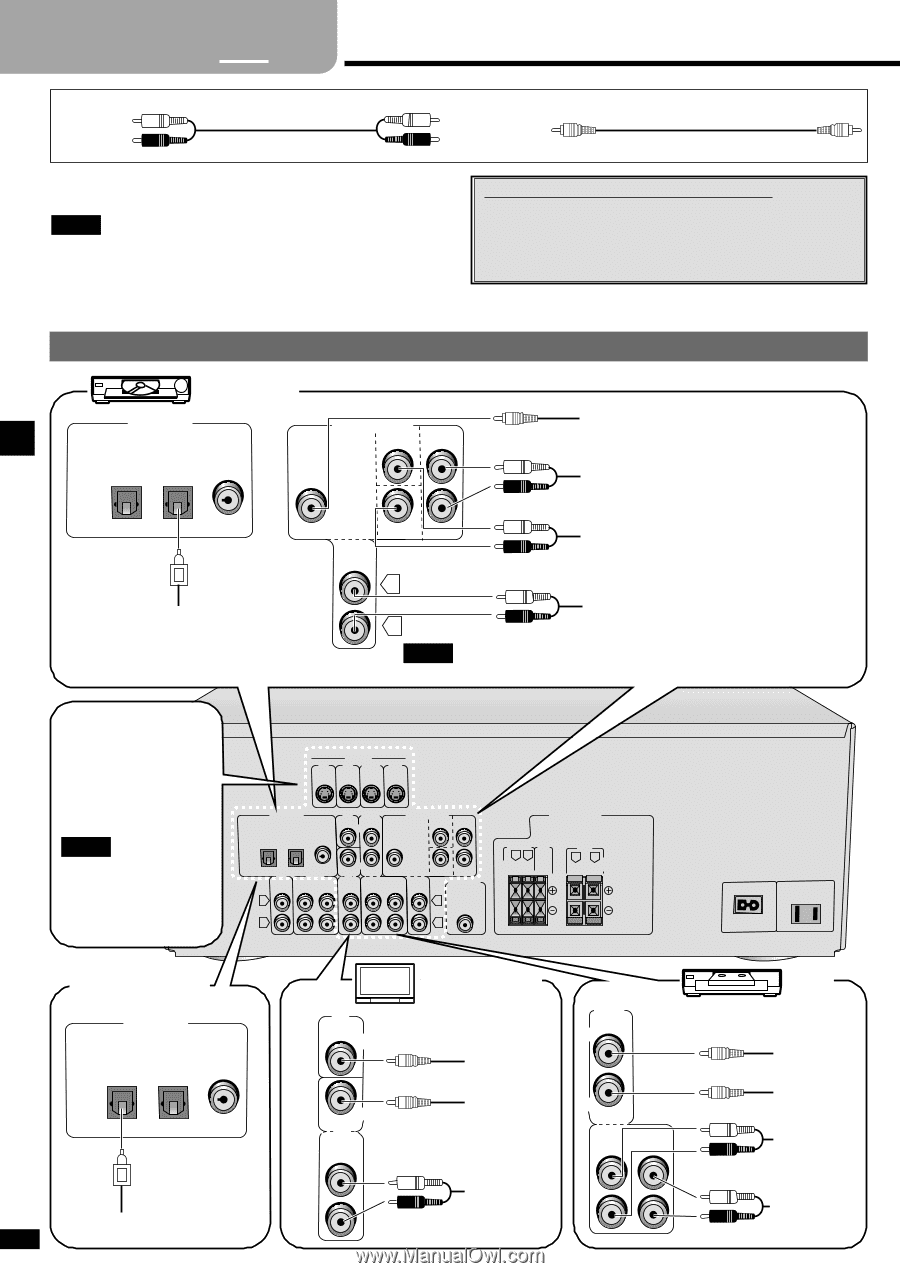
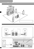
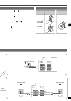
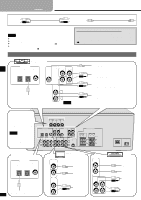
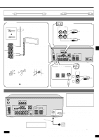
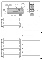
2 Step 1 3 4 Equipment connections Stereo connection cable White (L) Red (R) Video connection cable To connect equipment, refer to the appropriate operating instructions. Note ¡Do not bend the optical fiber cable. ¡Turn off all components before making any connections. ¡Use digital connection to enjoy Dolby Digital or DTS (\ page 10). ¡Use analog connection to enjoy sources that cannot be decoded on this unit and to record a source (\ pages 10 and 16). TV, VCR and DVD player Changing the digital input settings You can change the input settings for the digital terminals if necessary. Note the equipment you have connected to the terminals, then change the settings (\ page 9). DVD player DIGITAL IN OPTICAL1 OPTICAL2 COAXIAL (TV) (DVD) DVD/DVD 6CH CENTER SURROUND IN L VIDEO OUT AUDIO OUT (SURROUND L, R) IN R SUBWOOFER FRONT AUDIO OUT (CENTER, SUBWOOFER) DIGITAL AUDIO OUT L AUDIO OUT R (FRONT L, R) Note Connect to FRONT L, R if your DVD player does not have 6 channel output. Step 2 The S-VIDEO terminals Connections through these LOOP ANT HOLDER terminals provide higher quality pictures than through the video terminal. FM Note ANT 75Ω Video signals input iGnNDto the VIDEO terminals cannot be output from S-VLOIODP EO terminals or vice versEaAXM.T ANT S-VIDEO TV TV VCR1 DVD MONITOR IN IN IN OUT DIGITAL IN TV VCR1 OPTICAL1 OPTICAL2 COAXIAL MONITOR (TV) (DVD) OUT DVD/DVD 6CH CENTER SURROUND IN L IN CD TAPE TV REC PLAY (OUT) (IN) OUT L IN R SUBWOOFER FRONT IN SUBWOOFER OUT L SPEAKERS HAUT-PARLEURS SURROUND RL 6-8Ω EACH SPEAKER CHAQUE CENTER 6-8Ω FRONT R L 6-8Ω EACH SPEAKER CHAQUE R R RQT6847 Satellite receiver etc. DIGITAL IN OPTICAL1 OPTICAL2 COAXIAL (TV) (DVD) DIGITAL OUT 6 TV MONITOR OUT IN TV TV or monitor VIDEO IN VCR1 OUT VIDEO OUT IN OUT IN AUDIO OUT AC IN ∼ AC OUTLET VCR VIDEO IN VIDEO OUT AUDIO IN AUDIO OUT
-
 1
1 -
 2
2 -
 3
3 -
 4
4 -
 5
5 -
 6
6 -
 7
7 -
 8
8 -
 9
9 -
 10
10 -
 11
11 -
 12
12 -
13
-
14
-
15
-
16
-
17
-
18
-
19
-
20
 |
 |