Panasonic SCHT800V SAHT790V User Guide - Page 52
INFO, OTHER SPEAKER SETUP OPTIONS, Attaching to a wall, Fitting speaker stands optional
 |
View all Panasonic SCHT800V manuals
Add to My Manuals
Save this manual to your list of manuals |
Page 52 highlights
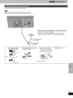
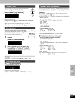
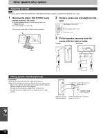
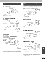
Other speaker setup options Attaching to a wall [Note] The wall or pillar on which the speakers are to be attached should be capable of supporting 10 kg (22 Ib.) per screw. 1 Remove the stand. (SC-HT810V only) BEFORE REMOVING THE STAND ≥Take the speaker cable out of the stand's hole if it is threaded through. ≥Lay the speaker on a soft cloth. Unscrew the screw with a Phillips-head screwdriver. 2 Screw a screw (not included) into the wall. 30-35 mm (13/16q-13/8q) ‰7.5-9.4 mm (19/64q-3/8q) 8-11 mm (3/8q-7/16q) Wall 3 Fit the speaker securely onto the screw with the hole or holes. Vertical Horizontal Stand 100 mm (315/16q) Fitting speaker stands (optional) Preparation ≥Remove the stand (SC-HT810V only ➡ step 1 above). ≥Ensure the stands meet these conditions before purchasing them. -Observe the diameter and length of the screws and the distance between screws as shown in the diagram. -The stands must be able to support over 10 kg (22 lb.). -The stands must be stable even if the speakers are in a high position. 5 mm (13/64q), pitch 0.8 mm (1/32q) 60 mm (223/64q) Speaker stand (not included) Attach the stands Plate thickness plus 7 to 10 mm with these holes. (plus 9/32q to 25/64q) RQT6951 52
-
 1
1 -
2
-
3
-
4
-
5
-
6
-
7
-
8
-
9
-
10
-
11
-
12
-
13
-
14
-
15
-
16
-
17
-
18
-
19
-
20
-
21
-
22
-
23
-
24
-
25
-
26
-
27
-
28
-
29
-
30
-
31
-
32
-
33
-
34
-
35
-
36
-
37
-
38
-
39
-
40
-
41
-
42
-
43
-
44
-
45
-
46
-
 47
47 -
 48
48 -
 49
49 -
 50
50 -
 51
51 -
 52
52 -
 53
53 -
 54
54 -
 55
55 -
 56
56 -
 57
57 -
58
-
59
-
60
-
61
-
62
-
63
-
64
 |
 |
