Panasonic TH-50PZ700 Operating Instructions - Page 9
Identifying Controls, Basic Connection
 |
View all Panasonic TH-50PZ700 manuals
Add to My Manuals
Save this manual to your list of manuals |
Page 9 highlights
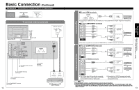
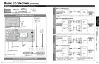
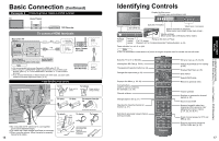
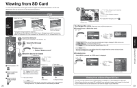
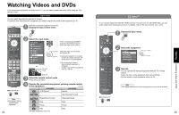
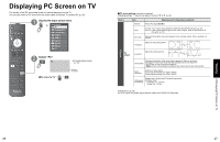
Basic Connection (Continued) Example 4 Connecting Home Theater and DVD recorder TV Home Theater DVD Recorder To connect HDMI terminals Back of the TV VIDEO DIGITAL AUDIO OUT 1 AV IN 2 or AUDIO IN Home theater (DIGITAL AUDIO IN) (When listening to TV audio) [ATSC only] Home theater (HDMI AV OUT) DIGITAL AUDIO IN HDMI AV OUT Home Theater (AV amp) Note •• It is recommended that you use Panasonic's HDMI cable. (P. 32) When Using the COMPONENT VIDEO OUT terminals or the S VIDEO OUT terminal, refer to p. 15 "To use COMPONENT terminals" or "To use S VIDEO • terminals". If you connect RAM theater or Player theater with HDMI cable, use audio cable instead of the optical digital audio cable. (p. 43) DVD Recorder HDMI AV IN HDMI AV OUT Cable Binding Instructions Cable clamper To fix Push until it clicks To release Press catch in and pull away AC cord To open To shut To remove from the TV To attach Band Push both side hooks To fasten To loosen Do not bundle the RF cable and AC cord together •(could cause distorted image). Fix cables with Cable clamper and Band as necessary. •When using the options, follow the option's assembly •manual to fix cables. 16 tab Insert Accessories Band (2) (Supplied with Pedestal) Identifying Controls Display the Main menu. Choose menu and submenu entry. SD CARD slot Switches TV/VIDEO Video Input 3 connector Selects channels in sequence (Move cursor up or down during menu mode.) Volume up/down (Move cursor right or left during menu mode.) POWER button Remote Swing up the door at "PULL". control C.A.T.S. sensor sensor Plasma C.A.T.S. (Contrast Automatic Tracking System). (p. 28) Power indicator (on: red, off: no light) Note •The TV consumes a limited amount of power as long as the power cord is inserted into the wall outlet. Switches TV to On or Standby Viewing from SD Card (p. 22-23) The equipment selection button (p. 24) Changes the input mode (p. 24) SUB MENU Displays Sub Menu (p. 20, 30) Colored buttons (used for various functions) (for example p. 22, 36) Channel up/down Changes aspect ratio (p. 21) Operates the Favorite channel list function. (p. 21) Switches to previously viewed channel and input modes. EZ Sync menu (p. 25, 32-33) Selects Audio Mode for TV viewing (p. 20) Displays Main Menu (p. 28) Exits menus Selects/OK/Change Returns to previous menu Volume up/down Displays or removes the channel banner (p. 20) Sound mute On/Off Numeric keypad to select any channel (p. 20) or press to enter alphanumeric input in menus. (p. 24, 25, 34, 36, 41) - Direct channel access for DTV and DBS (p. 20) External equipment operations (VCRs, DVDs, etc.) (p. 24) 17 Identifying Controls Basic Connection (TV + Home Theater + DVD Recorder) Quick Start Guide
-
 1
1 -
2
-
3
-
 4
4 -
 5
5 -
 6
6 -
 7
7 -
 8
8 -
 9
9 -
 10
10 -
 11
11 -
 12
12 -
 13
13 -
 14
14 -
15
-
16
-
17
-
18
-
19
-
20
-
21
-
22
-
23
-
24
-
25
-
26
-
27
-
28
-
29
-
30
 |
 |
