Panasonic WJ-GXD400 Installation Guide - Page 13
Rear view
 |
View all Panasonic WJ-GXD400 manuals
Add to My Manuals
Save this manual to your list of manuals |
Page 13 highlights
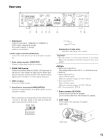
Rear view XX-XX-XX-XX-XX-XX AUDIO OUT VIDEO OUT OUT IN G q w e rt y 12V IN ui q Network port Connect a LAN cable. (100BASE-TX/1 000BASE-T) NTSC model: category 5e, straight PAL model: category 7, straight (Cable is not provided.) wAudio output connector (AUDIO OUT) Connect an audio device such as an amplifier, speaker, etc. e Video output connector (VIDEO OUT) Connect a video device such as a monitor. r SIGNAL GND terminal Connect this terminal with the SIGNAL GND terminals of the devices in the system for signal ground. When operating the decoder and the devices in the system without signal ground, oscillation or noise may be produced. t HDMI connector Connect an HDMI monitor. y Alarm/Control terminals (ALARM/CONTROL) Connect an external device or an alarm device such as a buzzer or a lamp. When connecting an external device, first remove 9 mm - 10 mm of the outer jacket of the cable and twist the cable core to prevent a short circuit. Output Input G Approx. 9 - 10 mm Specification of cable (wire): AWG #22 - #28 Single core, twisted Important: • Do not connect 2 or more wires directly to a terminal. When it is necessary to connect 2 wires or more, use a splitter. • Alarm reset input (IN 1): Non-voltage make contact (DC 4 - 5 V internal pull-up) • GND (G): • Alarm output (OUT 2): Open collector output (Maximum applied voltage: 24 V DC, 100mA) • Error output (OUT 1): Open collector output (Maximum applied voltage: 24 V DC, 100mA) • NC: Do not use.(IN 2, OUT 3) u Power connector (DC12V IN) Connect to the provided AC adapter. Do not connect other than the provided AC adapter. i Cable clamp Fix the cable of the provided AC adapter. Cable clamp Cable clamp 13
-
 1
1 -
2
-
3
-
4
-
5
-
6
-
7
-
 8
8 -
 9
9 -
 10
10 -
 11
11 -
 12
12 -
 13
13 -
 14
14 -
 15
15 -
 16
16 -
 17
17 -
 18
18 -
19
-
20
-
21
-
22
-
23
-
24
-
25
-
26
-
27
-
28
 |
 |
