Panasonic WJHD220 WJHD220 User Guide - Page 10
Rear View, Video Output Connector VIDEO OUT 1-8
 |
View all Panasonic WJHD220 manuals
Add to My Manuals
Save this manual to your list of manuals |
Page 10 highlights
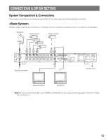
I Rear View #0 IN OUT AUDIO #2 #4 #6 #9 $0 IN 8 7 6 5 4 3 2 1 SPOT OUT ALARM/REMOTE OUT 8 7 6 5 4 3 2 1 VIDEO MULTI SCREEN OUT RS-232C MODE 10/100BASE-T DATA #1 #3 #5 #7 #8 $1 $2 $3 POWER ON SIGNAL GND OFF $4 #0 Audio Input Connector (AUDIO IN) An RCA standard jack that accepts an unbalanced -10 dBV, 10 kΩ line input audio signal supplied from an external device. #1 Audio Output Connector (AUDIO OUT) An RCA standard jack that supplies an unbalanced -10 dBV, 600 Ω line output audio signal to an external device. #2 Video Input Connector (VIDEO IN 1-8) Connectors 1-4 allow direct connection of the PSD cameras (video and commands multiplexed) while connectors 5-8 accept only normal video signals. A 75 Ω termination is made unless the video output terminal is connected. #3 Video Output Connector (VIDEO OUT 1-8) This BNC supplies a video signal looped through the video input terminal. Connectors 1-4 will output signals only when the recorder is turned on. #4 Spot Output Connector (SPOT OUT) This BNC supplies a full-screen live image signal to the spot monitor while recording or not recording. No playback or split image, setup menu, or OSD information is supplied via this connector. #5 Multiscreen Output Connector (MULTISCREEN OUT) This BNC provides the multiscreen monitor with the following video. • Live image: single spot, multi-split spot, single sequence, quad-split sequence • Playback image: single spot, multiscreen spot • OSD information: camera title, time and date, recorder status, alarm status The menu setup windows are also provided via this BNC. #6 Alarm/Remote Port (ALARM/REMOTE) This port accepts the alarm inputs 1 - 8, and remote controls while supplying status outputs. See ALARM/ REMOTE Connection for details. #7 RS232C Port (RS-232C) This 9-pin port is used to communicate with the personal computer when controlling the recorder, or updating the firmware installed in the recorder. See Serial Port Connections for cable wiring, and RS-232C Communication Protocol. #8 Mode Setup DIP Switch (MODE) A 6-bit switch is used for such system setups as disk formatting, PSD chain termination, and so forth. See DIP Switch Setting for details. #9 10Base-T/100Base-T (10/100BASE-T) This port is used to exchange control data with Ethernet via an Ethernet Hub. $0 Data Port (DATA) This port is used to communicate with external devices compatible with the PSD (Panasonic Security Data) protocol based on RS485. $1 Cooling Fan Prevents the temperature of the recorder from rising. Do not block the ventilation openings. $2 Power Switch (POWER ON OFF) This switch turns the power of the recorder on and off. $3 Signal Ground Terminal (SIGNAL GND) $4 Power Cord Is connected to an AC outlet. 10
-
 1
1 -
2
-
3
-
4
-
 5
5 -
 6
6 -
 7
7 -
 8
8 -
 9
9 -
 10
10 -
 11
11 -
 12
12 -
 13
13 -
 14
14 -
 15
15 -
16
-
17
-
18
-
19
-
20
-
21
-
22
-
23
-
24
-
25
-
26
-
27
-
28
-
29
-
30
-
31
-
32
-
33
-
34
-
35
-
36
-
37
-
38
-
39
-
40
-
41
-
42
-
43
-
44
-
45
-
46
-
47
-
48
-
49
-
50
-
51
-
52
-
53
-
54
-
55
-
56
-
57
-
58
-
59
-
60
-
61
-
62
-
63
-
64
-
65
-
66
-
67
-
68
-
69
-
70
-
71
-
72
-
73
-
74
-
75
-
76
-
77
-
78
-
79
-
80
-
81
-
82
-
83
-
84
-
85
-
86
-
87
-
88
-
89
-
90
-
91
-
92
-
93
-
94
-
95
-
96
-
97
-
98
-
99
-
100
-
101
-
102
-
103
 |
 |
