Panasonic WVCF324 WVCF324 User Guide - Page 11
Precautions, Installations and Connections
 |
View all Panasonic WVCF324 manuals
Add to My Manuals
Save this manual to your list of manuals |
Page 11 highlights
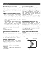
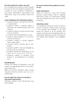
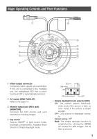
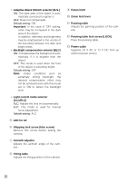
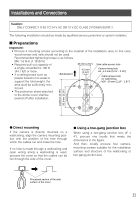
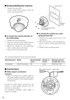
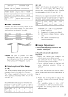
Installations and Connections Caution: ONLY CONNECT THIS TO 24 V AC OR 12 V DC CLASS 2 POWER SUPPLY. The following installation should be made by qualified service personnel or system installers. I Preparations Important: • Procure 4 mounting screws according to the material of the installation area. In this case, wood screws and nails should not be used. Recommended tightening torque is as follows. M4: 1.6 N·m {1.18 lbf·ft} • Required pull-out capacity of 46 mm {1.81"} Side cable access hole a single screw/bolt is 196 N {44.1 lbf} or more. • If a ceiling board such as plaster board is too weak to support the total weight, the 4.5 mm {0.18"} Camera fixing hole ø4 - 4.5 mm {0.16" - 0.18"} Cable access hole for wall/ceiling ø30 - 50 mm {1.18" - 1.97"} area shall be sufficiently rein- forced. • The protection sheet attached to the dome cover shall be peeled off after installation. ø146mm {5.75"} 83.5mm {3.29"} G Direct mounting If the camera is directly mounted on a wall/ceiling, align the camera mounting position with the position of the hole through which the cables run and make the hole. If no hole is made through a wall/ceiling and open wiring along a wall/ceiling is used, process the cover so that the cables can be run through the side of the cover. G Using a two-gang junction box When using a two-gang junction box (4" x 4"), procure one locally that meets the dimensions in the figure. And then, locally procure four cameramounting screws suitable for the installation surface and structure of the wall/ceiling or two-gang junction box. Processed section of the side surface of the cover 11
-
 1
1 -
2
-
3
-
4
-
5
-
 6
6 -
 7
7 -
 8
8 -
 9
9 -
 10
10 -
 11
11 -
 12
12 -
 13
13 -
 14
14 -
 15
15 -
 16
16 -
17
-
18
-
19
-
20
-
21
-
22
-
23
-
24
-
25
-
26
-
27
-
28
-
29
-
30
-
31
-
32
-
33
-
34
-
35
-
36
 |
 |