Panasonic WVCF324 WVCF324 User Guide - Page 12
Disassembling the Camera, Connections, To mount the camera directly on, the wall/ceiling
 |
View all Panasonic WVCF324 manuals
Add to My Manuals
Save this manual to your list of manuals |
Page 12 highlights
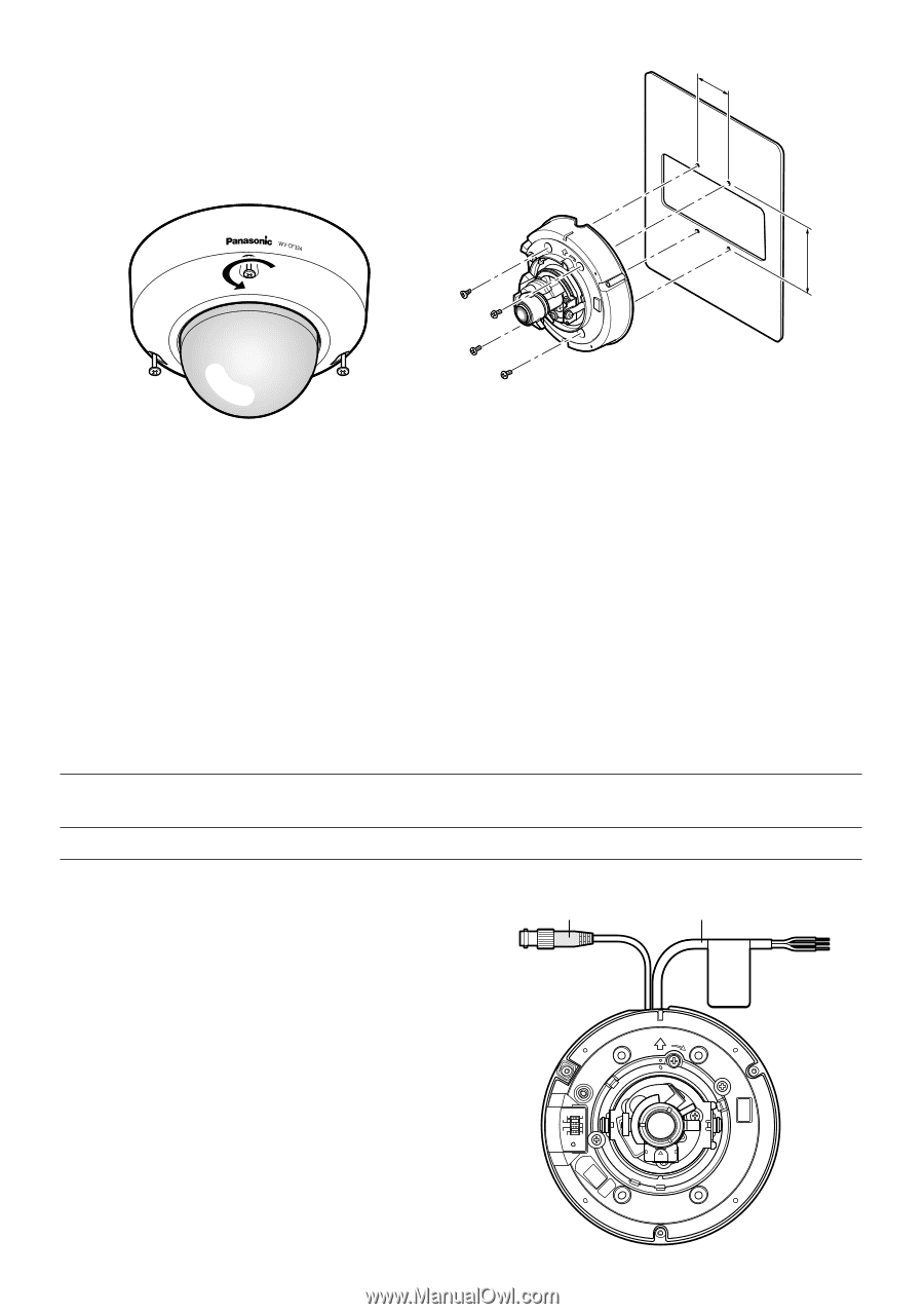
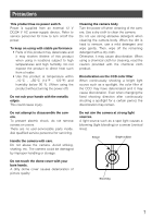
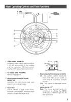
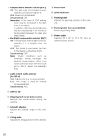
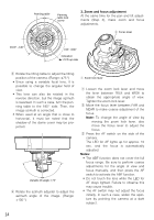
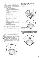
I Disassembling the Camera 1. Remove the top cover. Loosen three fixing screws of the top cover, and remove them. 46mm {1.81"} Camera mounting screw x4 (not supplied) 83.5mm {3.29"} G To mount the camera directly on the wall/ceiling 1. Prepare the mounting space. 2. Place the camera on the wall/ceiling and mark four screw positions with a pen. 3. Mount the camera on the wall/ceiling with 4 screws (procured locally). 4. Fasten all the mounting screws. G To mount the camera on a twogang junction box 1. Install the two-gang junction box on the wall/ceiling. 2. Mount the camera on the two-gang junction box with 4 screws (procured locally). 3. Fasten all the mounting screws. The mounting requirements are shown as follows. Mounting place Model Ceiling/wall (direct mounting) Recommended Number of screw screws M4 4 pcs. Minimum pull-out strength (per 1 pc.) 196 N {44.1 lbf} I Connections G Video output connection Important: • When connecting the coaxial cable to the video output connector, make sure that the connector of the coaxial cable is locked firmly. Connect the video output connector to the monitor or other system devices with the procured coaxial cable. The maximum extensible cable length is shown in the table. D/NB.S ON AFOFF BLC ALC ELC Video output connector Power cable MONITOR TOP LOCK 12
-
 1
1 -
2
-
3
-
4
-
5
-
6
-
 7
7 -
 8
8 -
 9
9 -
 10
10 -
 11
11 -
 12
12 -
 13
13 -
 14
14 -
 15
15 -
 16
16 -
 17
17 -
18
-
19
-
20
-
21
-
22
-
23
-
24
-
25
-
26
-
27
-
28
-
29
-
30
-
31
-
32
-
33
-
34
-
35
-
36
 |
 |