Panasonic WVCF324 WVCF324 User Guide - Page 13
Image Adjustment, Power connection, Cable Length and Wire Gauge
 |
View all Panasonic WVCF324 manuals
Add to My Manuals
Save this manual to your list of manuals |
Page 13 highlights
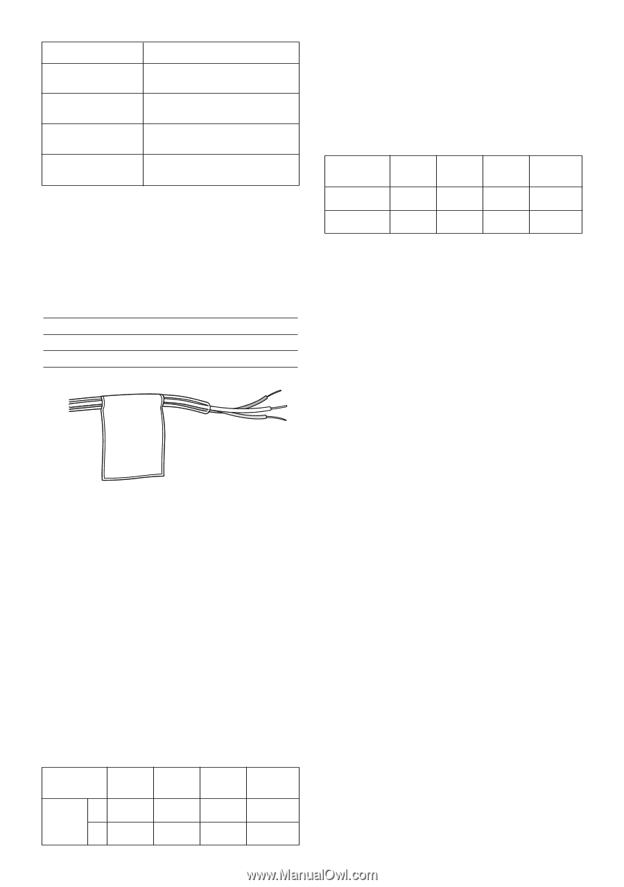
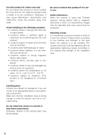
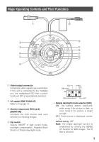
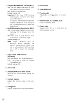
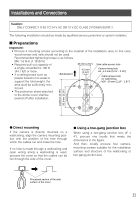
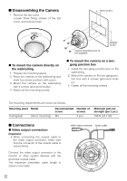
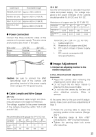
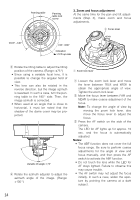
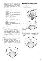
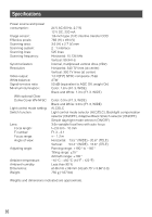
Cable type Extensible length RG-59/U (3C-2V) Approx. 250 m {825 ft} RG-6/U (5C-2V) Approx. 500 m {1 650 ft} RG-11/U (7C-2V) Approx. 600 m {1 980 ft} RG-15/U (10C2V) Approx. 800 m {2 640 ft} G Power connection Connect the three-conductor cable of the camera to the power supply. The wire colors and functions are shown in the table. Wire color Brown Blue Green/yellow 12 V DC Positive Negative Grounding 24 V AC Live Neutral Grounding 12 V DC Use the formula below to calculate the power cable and power supply. The voltage supplied to the power terminals of the camera should be within 10.8 V DC and 16 V DC. Resistance of copper wire [at 20 °C {68 °F}] Copper wire size (AWG) Resistance Ω/m Resistance Ω/ft #24 #22 #20 #18 (0.22 mm2) (0.33 mm2) (0.52 mm2) (0.83 mm2) 0.078 0.050 0.03 0.018 0.024 0.015 0.009 0.005 10.8 V DC ≤ VA - 2 (R x I x L) ≤ 16 V DC L: Cable length (m) R: Resistance of copper wire (Ω/m) VA: DC output voltage of power supply unit I: DC current consumption (A) See specifications. Caution: Be sure to connect the GND (grounding) lead of the camera and grounding terminal of the power supply when using a 24 V AC power source. G Cable Length and Wire Gauge 24 V AC The recommended cable length and thickness are shown in the table for reference. The voltage supplied to the power terminals of the camera should be within 19.5 V AC and 28 V AC. Recommended wire gauge for 24 V AC line. Copper wire #24 #22 #20 #18 size (AWG) (0.22 mm2) (0.33 mm2) (0.52 mm2) (0.83 mm2) Length of (m) 20 30 45 75 Cable (Approx.) (ft) 66 100 150 250 I Image Adjustment 1. Connect an adjusting monitor to the monitor output jack. 2. Pan, tilt and azimuth adjustment Important: • Adjust the camera after removing the shipping lock screw (blue screw). • Do not touch the iris motor. Failure to observe this may cause trouble. • Do not hold the camera by the lens unit when adjusting panning, tilting, or azimuth. At the same time for the pan and tilt adjustments, make zoom and focus adjustments of Step 3. q Rotate the panning table to adjust the panning position of the camera. (Range: 320 °) • The adjusting range is from +180 ° (clockwise) to -140 ° (counterclockwise). • Tighten the panning table lock screw after adjusting. 13
-
 1
1 -
2
-
3
-
4
-
5
-
6
-
7
-
 8
8 -
 9
9 -
 10
10 -
 11
11 -
 12
12 -
 13
13 -
 14
14 -
 15
15 -
 16
16 -
 17
17 -
 18
18 -
19
-
20
-
21
-
22
-
23
-
24
-
25
-
26
-
27
-
28
-
29
-
30
-
31
-
32
-
33
-
34
-
35
-
36
 |
 |