Philips DVDR75 Quick start guide - Page 3
Connecting the DVD Recorder with a Cable Box, with Audio/Video Cables
 |
View all Philips DVDR75 manuals
Add to My Manuals
Save this manual to your list of manuals |
Page 3 highlights
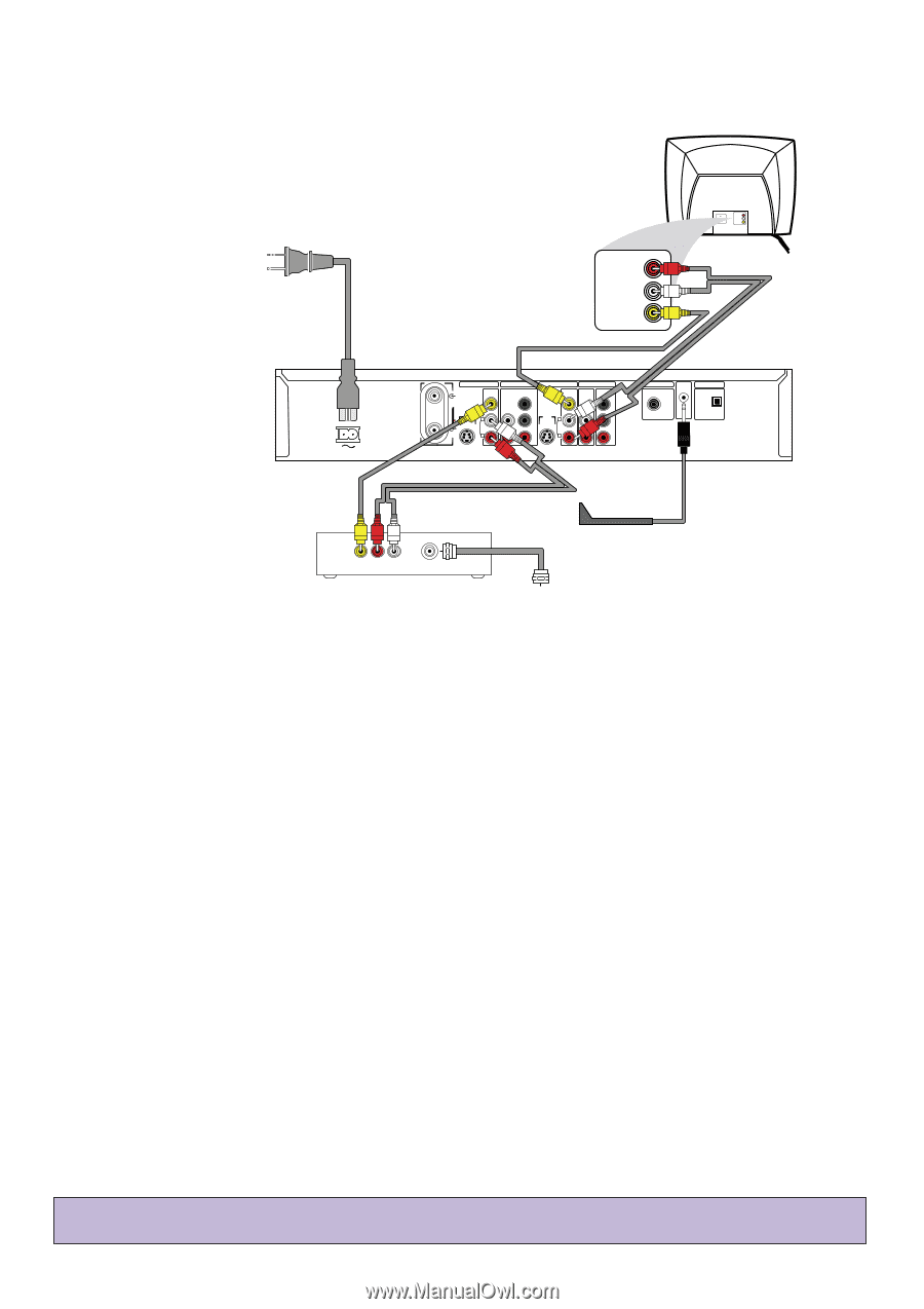
Connecting the DVD Recorder with a Cable Box (with Audio/Video Cables) Power cord to the DVD Recorder's RIGHT AUDIO IN MAINS jack and LEFT AUDIO IN VIDEO IN to a power outlet Audio and Video cables to the DVD Recorder's red/white AUDIO OUT 2 and yellow VIDEO (CVBS) OUT2 jacks and to the TV's AUDIO and VIDEO IN jacks RIGHT AUDIO IN LEFT AUDIO IN VIDEO IN MAINS IN - EXT 2 VIDEO (CVBS) ANTENNA IN - EXT 1 AUDIO COMPONENT VIDEO Y OUT 2 OUT 1 480p/480i VIDEO AUDIO COMPONENT (CVBS) VIDEO Y S-VIDEO S-VIDEO (Y/C) (Y/C) L PB L PB AUDIO AUDIO TV R PR R PR IN - EXT 1 COAX OUT G-LINK DIGITAL AUDIO OUT OPTICAL OUT Audio and Video cables from the AUDIO and VIDEO OUT jacks of the Cable Box to the DVD Recorder's red/white AUDIO IN -EXT 2 and yellow VIDEO (CVBS) IN - EXT 2 jacks VIDEO AUDIO AUDIO IN OUT OUT OUT R L To front of Cable Box (not used with Satellite) Cable TV signal to the IN jack on the Cable Box Your Cable Box may have Audio and Video Out jacks instead of a single ANTENNA OUT, TO TV, or RF OUT jack as shown on page 2 of this Guide. If so, use the Audio and Video Out jacks to connect the Cable Box to your DVD Recorder. 1 Connect the Cable TV signal to the IN jack on your Cable Box. 2 Connect a composite video cable (usually yellow) to the VIDEO OUT jack on the Cable Box. Connect the other end of the same video cable to the yellow VIDEO (CVBS) IN - EXT 2 jack on the Recorder. 3 Connect audio cables to the right/left AUDIO OUT jacks on the Cable Box. Connect the other ends of the same audio cables to the Recorder's red/white AUDIO (right/left) IN - EXT 2 jacks. Match the cable colors to the jack colors. 4 Connect the supplied audio cables (red/white) to the red/white, right/left AUDIO OUT 2 jacks on the DVD Recorder and to the right/left AUDIO IN jacks on your TV. Match the cable colors to the jack colors. 5 Connect the supplied video cable (yellow) to the DVD Recorder's yellow VIDEO (CVBS) OUT 2 jack and to the TV's VIDEO IN jack. 6 You will need the G-Link cable in order to use the GUIDE Plus+® System. Connect the supplied G-Link cable to the G-LINK jack on the rear of the DVD Recorder. (Remove the Demo Pin first if it is still attached to the GLINK jack.) Place the sensor of the G-Link cable in front of the Cable Box so it faces the remote sensor of your Cable Box. The G-Link cable's sensor should be within one inch of the front of your Cable Box. 7 Connect the supplied power cord to the MAINS (AC Power) jack on the rear of the DVD Recorder. Connect the power cords of the Recorder,TV, and Cable Box to a power outlet. The first time you connect the Recorder's power cord, the features of the Recorder will scroll across its display panel. This will stop when you turn on the DVD Recorder's power. 8 Press STANDBY y to turn on the DVD Recorder. Set the Recorder to EXT 2 (because those are the jacks to which you connected the Cable Box). (To get to EXT 2, go to channel 1, then press 9CH- until you reach the EXT 2 channel.) Turn on the TV; set it to the Audio/Video In channel. You should see the Initial Setup menu on the TV the first time you turn on the DVD Recorder. See pages 4-5 of this Quick-Use Guide to set up the DVD Recorder for the first time. • If you have a Satellite Receiver, the hookup resembles that of a Cable Box. However, you cannot use the GUIDE Plus+® System, so do not connect the G-Link cable. 3
-
 1
1 -
 2
2 -
 3
3 -
 4
4 -
 5
5 -
 6
6 -
 7
7 -
 8
8
 |
 |