Pioneer 504CMX Command Reference - Page 13
GET Commands - 50
 |
UPC - 012562689784
View all Pioneer 504CMX manuals
Add to My Manuals
Save this manual to your list of manuals |
Page 13 highlights
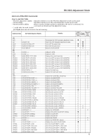
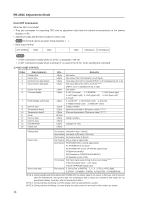
RS-232C Adjustment Mode 5.5.6 GET Commands What are GET commands? • They are commands for outputting TXD such as adjustment data from the internal microcomputer of the plasma display to a PC. • Adjustment data and the like is output in ASCII code. Note Command names are given inside brackets < >. • Data output format STX (02hex) Data Data ···· Data Checksum ETX (03hex) Notes • A GET command is invalid when no ID No. is assigned to the set. • A GET command is invalid when a wildcard (*) is used in the ID No. when sending the command. 1) (GET STATUS) Order 1 2 3 4 Data Contents Display data Power data Input function data (main) Input function data (sub) 5 Screen size data 6 2-screen display 7 FUNCTIONAL LOCK data 8 Dummy data 9 Temperature data 2 10 Temperature data 3 11 Serial 12 Dummy data 13 Dummy data 14 HOURMETER 15 Check sum Size 3 Byte 3 Byte 3 Byte 3 Byte 1 Byte 1 Byte 1 Byte 3 Byte 3 Byte 3 Byte 15 Byte 3 Byte 3 Byte 5 Byte 2 Byte Remarks See below See below (The third character is sub input.) Input data when GST is received (INPUT1 to 5 is displayed as IN1 to 5.) Sub input data when GST is received Note 3) (INPUT 1 to 5 is displayed as IS1 to IS5.) See below 0: OFF (1 screen) 1: 2-SCREEN 2: PinP (lower right) 3: PinP (upper right) 4: PinP (upper left) 5: PinP (lower left) 6: PoutP 0: LOCK OFF 1: BUTTONS LOCK 2: IR LOCK 3: IR&BUTTONS LOCK 4: MEMORY LOCK (3-digit number) (Internal temperature: Reference value) °C Note 1) (External temperature: Reference value) °C Note 1) (3-digit number) Displays the time. Display data Power data Screen size data First character Generation data: 4 (fixed) Second character Inch data: 4 (43 inch), 5 (50 inch) Third character Destination data: M (fixed) First character Power state & signal state Second character PN (POWER ON & normal signal input) PL (POWER ON & no input) PO (POWER ON & OUT OF RANGE signal input) SN (Normal standby) SW (Standby by POWER MANAGMENT) SS (Standby by SD or PD) Third character Sub input signal state during multi-screen display Note 2) N (Normal signal input) L (No input) O (OUT OF RANGE signal input) First character 0; Dot by Dot or PARTIAL 1; 4 : 3 2; FULL or FULL1080i 3; ZOOM 4;CINEMA 5;WIDE 8;FULL1035i 9; UNDERSCAN NOTE 1) During standby and immediately after POWER ON, the proper value is not output. In this case, wait a moment after the POWER ON, then get the data. The temperature data is output as a reference (the values are not guaranteed values). Normally, refer to temperature data 3. NOTE 2) During standby and during 1-screen display, dummy data (symbol) is output. NOTE 3) During standby and during 1-screen display the values stored in memory for the product are output. 11
-
 1
1 -
2
-
3
-
4
-
5
-
6
-
7
-
 8
8 -
 9
9 -
 10
10 -
 11
11 -
 12
12 -
 13
13 -
 14
14 -
 15
15 -
 16
16 -
 17
17 -
 18
18
 |
 |
