Pioneer 504CMX Command Reference - Page 9
Command name, AJY 232C integrator Display, RS-232C, Adjustment, Validity, Normal, Numerical, Direct
 |
UPC - 012562689784
View all Pioneer 504CMX manuals
Add to My Manuals
Save this manual to your list of manuals |
Page 9 highlights
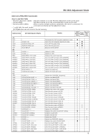
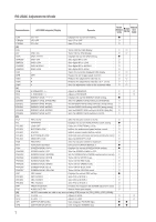
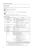
RS-232C Adjustment Mode Command name AJY (232C integrator) Display Remarks RS-232C Adjustment Validity Normal Validity Numerical Direct Validity CTR CTRS00 CTRS01 [D] DIN DIY DNR DNRS00 DNRS01 DNRS02 DNRS03 DOF DPR DW0 DWn DWF [E] ENH ENV ESV ESVS00 ESVS01 ESVS02 ESVS03 ESVS04 [F] FCA FCL FCLS00 FCLS01 FCLS02 FCLS03 FCLS04 FCM FDT FMK FMKS00 FMKS02 FMKS03 FMKS04 FMKS05 FMKS06 FMKS07 FRC FRCS01 FRCS02 FRCS03 FRP FXO [G] GHI GLW GPI GPS CTI: ### CTI: OFF CTI: ON Displays the current CTI setting. ¶ Sets CTI to OFF. ‡ Sets CTI to ON. ‡ OSD: ON DNR: ###### DNR: OFF DNR: LOW DNR: MIDDLE DNR: HIGH - DPR # # # Turns OFF the OSD display. Turns ON the OSD display. Displays the current DNR setting. Sets digital NR to ON. Sets digital NR to LOW. Sets digital NR to MIDDLE. Sets digital NR to HIGH. Clears the currently displayed OSD display. Resets the still image repeat function. Reduces the adjustment value by 10. Reduces the adjustment value by n (n = 1 to 9). Sets the adjustment value to the minimum value. H. ENHANCE: ∗∗∗ Adjusts H ENHANCE. ‡ ‡ V. ENHANCE: ∗∗∗ Adjusts V ENHANCE. ‡ ‡ ENERGY SAVE Displays the current ENERGY SAVE setting. ¶ ENERGY SAVE: STANDARD Sets the ENERGY SAVE setting to STANDARD. ‡ ENERGY SAVE: MODE1 Sets the ENERGY SAVE setting to MODE 1 (energy saving). ‡ ENERGY SAVE: MODE2 Sets the ENERGY SAVE setting to MODE 2 (energy saving). ‡ ENERGY SAVE: MODE3 Sets the ENERGY SAVE setting to MODE 3 (long life). ‡ ENERGY SAVE: AUTO Sets the ENERGY SAVE setting to AUTO. ‡ FAN: AUTO Sets the fan rpm control to AUTO. ‡ ######### Displays the current FUNCTIONAL LOCK setting. ¶ LOCK OFF Clears the FUNCTIONAL LOCK. ‡ BUTTONS LOCK Inhibits the main-control panel button control. ‡ IR LOCK Inhibits remote-control button control. ‡ BUTTONS&IR LOCK Inhibits both main-control panel and remote-control button control. ‡ MEMORY LOCK Sets the MEMORY LOCK. ‡ FAN: MAX Sets the fan rpm control to maximum. ‡ FUNCTION DEFAULT Executes FUCNTION DEFAULT. ¶ SCREEN MASK: ##### Displays the current SCREEN MASK setting. ¶ SCREEN MASK: OFF Sets the SCREEN MASK to OFF. ‡ SCREEN MASK: INVERSE Sets the SCREEN MASK to INVERSE (negative-positive inversion). ‡ SCREEN MASK: WHITE Turns ON the WHITE mask. ‡ SCREEN MASK: RED Turns ON the RED mask. ‡ SCREEN MASK: GREEN Turns ON the GREEN mask. ‡ SCREEN MASK: BLUE Turns ON the BLUE mask. ‡ SCREEN MASK: YELLOW Turns ON the YELLOW mask. ‡ FRC: ##### Displays the current FRC setting. ¶ FRC: MODE1 Sets FRC to MODE 1. ‡ FRC: MODE2 Sets FRC to MODE 2. ‡ FRC: MODE3 Sets FRC to MODE 3. ‡ FRESH POSITION Initializes the integrator and SCREEN adjustment values. ‡ AUDIO OUT: FIX Selects fixed audio output. ‡ ## GET commands are valid in any state including STB (except for [GPI], [GPS], [GSS], [GWB]). G HIGH: ∗∗∗ Adjusts G HIGH. ‡ ‡ G LOW: ∗∗∗ Adjusts G LOW. ‡ ‡ (GET PICTURE DATA) Gets integrator PICTURE data. ¶¶ (GET POSITION DATA) Gets integrator SCREEN data. ¶¶ 7
-
 1
1 -
2
-
3
-
 4
4 -
 5
5 -
 6
6 -
 7
7 -
 8
8 -
 9
9 -
 10
10 -
 11
11 -
 12
12 -
 13
13 -
 14
14 -
15
-
16
-
17
-
18
 |
 |