Pioneer 7000 Owner's Manual - Page 16
Connections - mixer
 |
UPC - 012562565330
View all Pioneer 7000 manuals
Add to My Manuals
Save this manual to your list of manuals |
Page 16 highlights
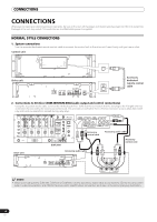
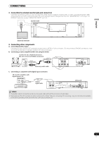
CONNECTIONS CONNECTIONS Whenever connecting or disconnecting components, be sure to first turn off the power and disconnect the power cord from its outlet first. Damage to the unit may result if connections are modified while power is supplied. NORMAL STYLE CONNECTIONS 1. System connections Use the provided dedicated remote control cable to connect the control unit to the drive unit. Insert firmly until you hear a click. Control unit PC 5V MONITOR OUT REMOTE CONTROL Drive unit AC IN PC USB1 DIGITAL OUT BA B AUDIO OUT L R A AUDIO OUT L R CONTROL CONTROL REMOTE CONTROL REMOTE CONTROL Accessory dedicated remote control cable 2. Connections to DJ mixer (DJM-3000/DJM-800) (audio output and control connections) Using the accessory audio cable, connect the white plug to the L (left) channel connector and the red plug to the R (right) channel connector. By connecting the accessory control cord, this unit can be controlled from a Pioneer DJ-mixer so as to allow fader start play and back cue operations (except during relay play). Drive unit Accessory control cord DJM-3000 Accessory audio cable Accessory audio cable Accessory control cord MEMO • When connecting to the DJM-300, DJM-500 or DJM-600, use the accessory audio cable to connect the CD1 to the drive unit's side A output connectors, and CD2 to the drive unit's side B output connectors as shown in the accompanying illustration. 16 En
-
 1
1 -
2
-
3
-
4
-
5
-
6
-
7
-
8
-
9
-
10
-
 11
11 -
 12
12 -
 13
13 -
 14
14 -
 15
15 -
 16
16 -
 17
17 -
 18
18 -
 19
19 -
 20
20 -
 21
21 -
22
-
23
-
24
-
25
-
26
-
27
-
28
-
29
-
30
-
31
-
32
-
33
-
34
-
35
-
36
-
37
-
38
-
39
-
40
-
41
-
42
-
43
-
44
-
45
-
46
-
47
-
48
-
49
-
50
-
51
-
52
-
53
-
54
-
55
-
56
-
57
-
58
-
59
-
60
-
61
-
62
-
63
-
64
-
65
-
66
-
67
-
68
-
69
-
70
-
71
 |
 |
